
Related Manuals for Aseptico AEU-425FO Transport II


Summary of Contents for Aseptico AEU-425FO Transport II
- Page 1 OPERATION and MAINTENANCE INSTRUCTION MANUAL AEU-425FO Transport II Portable Dental System With Fiber Optics...
-
Page 2: Table Of Contents
Figure 1 - Motor Connection ... .4 International (425) 487-3157 • Toll Free(800) 426-5913 www.aseptico.com • info@aseptico.com Figure 2 - Handpiece Alignment ..4 Figure 3 - Motor Endcap . -
Page 3: Introduction
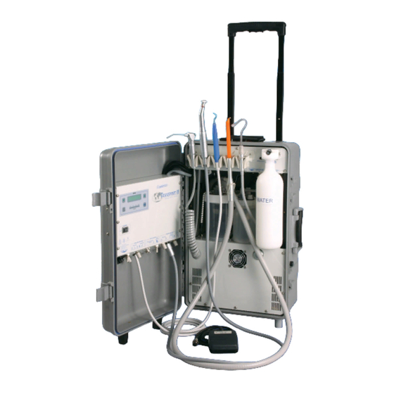
Your new Aseptico Transport II Portable Dental System is the finest portable electric dental system available. The AEU-425FO features a high-torque brushless micro motor with digital speed control, a 3-way air/water syringe, HVE and saliva ejector vacuum systems, a self contained water system, oilless air compressor, and Congratulations vacuum pump. -
Page 4: Specifications
SPECIFICATIONS: Size: 10.5” x 14.5” x 24” (27 cm x 36 cm x 61 cm) 1.81 cu. ft. (0.05 m 3) Volume: Weight: 52.5 lbs (23.8 kg) Power Source: AC Dual Voltage Auto-Switching 120V / 230V at 50Hz/60Hz Power Rating: 800 W Operating Pressure: 45 - 50 PSI (344 kPa) -
Page 5: Safety Precautions
SAFETY PRECAUTIONS: Aseptico accepts no liability for direct or consequential injury or damage resulting from improper use, arising in particular through the non-observance of the operating instructions, or improper preparation and maintenance. WARNING: Sterilize before first and all uses. Clean, disinfect, and sterilize new or repaired handpieces and instruments before first use. -
Page 6: Setting Up The Unit
SETTING UP THE UNIT: NOTE: The AEU-425FO is manufactured FIG. 2 - HANDPIECE ALIGNMENT- (Bulb Cover with 6.3A (250V rated) fuses installed, if Removed) operating with a 230V power source, MOTOR / HANDPIECE ALIGNMENT change to the 3.15A fuses before operation. 1. - Page 7 10. Place the small Waste Tank in the unit electrical waste container connections (see with the small gray connector towards the Figs. 4 & 8). Secure the tank by running front. Attach the gray hose coming from the bungee cord from the hooks on the above to the white connector.
- Page 8 FIG. 7 - AEU-425FO LEFT SIDE FOOT SWITCH RECEPTACLE OPTIONAL SCALER INTENSITY SETTING ADJUSTMENT OPTIONAL SCALER ON/OFF SWITCH ELECTRIC CONTROL CONSOLE HANDPIECE COOLANT FLOW POWER SWITCH ADJUSTMENT HANDPIECE LIGHT INTENSITY ADJUSTMENT POWER CORD RECEPTACLE FUSE PANEL/ FUSE HOLDERS MOTOR RECEPTACLE OPTIONAL SCALER HANDPIECE COOLANT COOLANT FLOW ON/OFF SWITCH...
- Page 9 FIG. 8 - AEU-425FO RIGHT SIDE FULL WASTE CONTAINER INDICATOR LIGHT PRESSURE GAUGE VACUUM HOLDER TOGGLE SWITCHES VACUUM AUTOMATIC ON/OFF TOGGLE SWITCHES WATER SUPPLY ON/OFF TOGGLE WASTE CONTAINER SWITCH AIR RESERVE BOTTLE CONNECTIONS (Behind Water Bottle) WATER SUPPLY BOTTLE 3-WAY SYRINGE STORAGE SALIVA EJECTOR WASTE CONTAINER BUNGEE CORDS COMPRESSOR INTAKE AIR FILTER HVE WASTE CONTAINER...
-
Page 10: Operation Functions
OPERATION FUNCTIONS: 1. Power Switch: Controls power on/off to console. When clockwise to decrease water flow and the AEU-425FO is turned on, the Electric counterclockwise to increase water flow. Control Console will light. 6. Handpiece Coolant Air - Switches the air 2. - Page 11 Press the right (Air) button on the 12. Water Supply Bottle: 3-Way Air/Water Syringe or open the The Aseptico AEU-425FO incorporates a low vacuum, with unit power off, to self contained pressurized water system. depressurize the air reserve tank.
- Page 12 OPERATION FUNCTIONS (continued): IMPORTANT NOTE: To prevent the HVE and Low Volume (Saliva Ejector) compressor system from running excessively, ensure that the vacuum heads are firmly cradled in their holders after each use and that their spring-loaded control levers are toggled ‘Off’’.
-
Page 13: Operation
OPERATION: After the unit has been set up and you have made yourself familiar with the operation functions, you are ready for operation as follows: 3b. Screw on a sterile Instrument Tip to the 1. Turn the power switch on the front of the Scaler Handpiece and tighten it firmly. -
Page 14: Sterilization & Maintenance
STERILIZATION AND MAINTENANCE: HANDPIECES - Thorough cleaning and lubrication of CAUTION FOR ALL STERILIZATION: handpieces after each use and before sterilization is • Do not submerge in any solutions. very important to ensure proper operation and service • Do not use ultrasonic cleaners. life of the handpiece. - Page 15 VACUUM SySTEM: WATER LINES: The HVE and Saliva Ejector Valves are fully Disinfect the water lines weekly. Prepare a autoclavable. Remove the valves from the 1:10 bleach solution (1 part household bleach hoses before autoclaving. to 10 parts water). Remove water reservoir and discard residual water.
- Page 16 STERILIZATION AND MAINTENANCE (continued): SyRINGE TIPS: The Three-Way Air/Water Syringe features quick-change autoclavable tips: To remove a tip, press on the locking collar surrounding the tip socket and pull the used tip straight out of the socket (see Fig. 9). To insert a new tip, press locking collar and push tip into socket as far as it will go.
-
Page 17: Changing The Fuse
CHANGING THE FUSE: SECONDARy FUSES WARNING: Turn the power off and unplug the Unscrew each fuseholder from below the unit before following the steps below. Inlet connector. Changing the fuse: PRIMARy FUSES Replacement Fuses: 0.63A, 250V slo-blo fuses NOTE: The AEU-425FO is manufactured (Fuse size: 5 x 20mm) with 6.3A (250V rated) fuses installed, if Replace the Fuseholders. -
Page 18: Symbol Definitions
SYMBOL DEFINITIONS: Type B Equipment Scaler Attention, consult Electric Handpiece accompanying documents Foot Switch Dangerous Voltage Toggle-Select Switch Alternating current Adjustment Switches Protective earth (ground) IPX1 Protect Against Dripping Water Handpiece Coolant Handpiece Coolant Air Serial Number Do Not Throw Into Trash... -
Page 19: Troubleshooting
TROUBLESHOOTING: Problem: Correction: Console does not light when turned on: Check console to power connection. Check that voltage is proper voltage. Check fuse. If blown, replace with 6.3A/250V slo-blo fuse for 120V operation, & 3.15A/250V slo-blo fuse for 230V operation. Check secondary fuses. -
Page 20: Warranty
Aseptico's sole obligation under product warranty is (at its sole option and discretion) to repair or replace any defective component or product in part or whole. Aseptico shall be the sole arbiter of such action.
Need help?
Do you have a question about the AEU-425FO Transport II and is the answer not in the manual?
Questions and answers