
Related Manuals for Aseptico TRANSPORT II


Summary of Contents for Aseptico TRANSPORT II
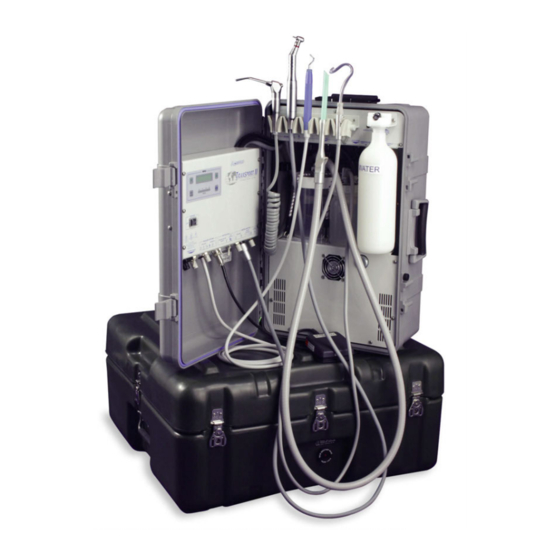
- Page 1 AEU-425CF AEU-425CFH Portable Dental System NSN: 6520-01-508-9583 TRANSPORT II SERVICE MANUAL & PARTS LIST...
-
Page 2: Table Of Contents
Specifications ............22 P.O. Box 1548 * Woodinville, WA 98072-1548 1-800-426-5913 * 425-487-3157 * Fax: 425-487-2608 email: info@aseptico.com * Internet: www.aseptico.com Page i Printed In The USA... -
Page 3: General Service Information
Electrical parts are called out by Aseptico part number in the ON position, the air pilot is activated allowing air in the assembly drawings. Parts, with photo callouts, are to flow to the vacuum pump. -
Page 4: Cleaning & Lubrication
Inspection and Operation Verification - Cont’d The system has two ways of removing moisture from the To verify the scaler, switch the SCALER/MOTOR air. A removable air chamber and a drainable filter selector switch (Fig. 5) to SCALER. With a tip on the prior to the syringe. -
Page 5: Disassembly
DISASSEMBLY ELECTRONICS MODULE: Reassembly is done in reverse order. Ensure that spac- Lay unit down. Open cover and remove Electronics ers are present on #4 standoffs prior to installing Module’s six Board. Reconnect all connectors. Install 1/16” cable ties Figure 6 mounting approximately where previously installed. -
Page 6: Toggle Valves
DISASSEMBLY - Cont’d FOOT SWITCH RECEPTACLE (PN 875026): TOGGLE VALVES (PN 730010 - Qty 3): Remove cable connector from Power/Display Board There are three Toggle Valves on Electronics Module: (see Fig. 11). Remove ground wire from ground stud 1.) Scaler Coolant On/Off Switch; 2.) Handpiece with 5/16”... -
Page 7: Scaler/Motor Toggle Switch
Re-assembly is done in the reverse order. Note: Ensure Figure 13 Scaler Assy that the common-marked side of water Solenoid is con- nected to line coming from Plumbing Module. SCALER/MOTOR TOGGLE SWITCH (PN 875041): Remove Toggle Switch 10-pin cable connector from Power/Display Board (see Fig. -
Page 8: Three-Way Solenoid
DISASSEMBLY - Cont’d THREE-WAY SOLENOID (PN 730474): Figure 16 Note the orientation of Three-Way Solenoid on Scaler plate (see Fig. 15). Remove tubing at Three-Way Solenoid. Remove Motor/Scaler cable connector on Power/ Display Board. Remove red and black wires Cover coming from Solenoid. -
Page 9: Capacitor
Figure 18 Figure 17 Pressure Tube Syringe Filter Air Filter Clamp Hoses (under plate) Filter Syringe Filter Plate Water Line Pressure Tube Capacitor Wrap Flow Plumbing Block Chassis • SYRINGE AIR FILTER (PN 730495): Remove the two tubes going to Filter (see Fig. 18). (Note: Removal of tubes is easier if heated slightly with Flat heat shrink gun.) With 3/32"... -
Page 10: Air Pilot Valve
crimp on terminals (P/N 860102) when reattaching. applied to fittings. Figure 19 Solenoid Air Reservoir Air Filter Reassemble in the reverse order. Tube • PRESSURE SENSOR (PN830067): Remove tube to Pressure Sensor (see Fig. 21). Remove wire connectors going to Pressure Sensor. Remove two screws holding wires from Pressure Sensor to Relay. -
Page 11: Syringe
PLUMBING CHASSIS - Cont’d WASTE CONTAINER MODULES Saliva and High Volume Waste Container Figure 21 FLOAT SENSOR CONNECTOR (PN 860080): Tube to Pressure Disassemble Float Sensor Connectors by trimming Sensor Sensor Tube Fitting back heat shrink and cutting wires to Connectors (see Fig. -
Page 12: Parts List
(Inside Container) (Inside Container) (Inside Container) (Inside Container) (Note: Item No. 35 Shown on Page 20) Page 10... - Page 13 ITEM DESCRIPTION PART NO. AEU-425CF FINAL ASSY 120284 LABEL MYLAR AEU-425 WATER 420299 BOTTLE .75L ROTO-MOLDED HDPE 730657 LABEL MYLAR AEU-425 AIR 420307 FTN 1/4 CLEAR SLEEVE (BINSTOCK) 730042 FILTER 10-32 THREAD STAINLESS 730326 FTN BARB 10-32 X 1/8 BRT/NKL (BINSTOCK) 730073 GASKET NYLON #10 (BINSTOCK)
- Page 14 63 64 216 6 Page 12...
- Page 15 ITEM DESCRIPTION PART NO. FAN 24V 23.3CFM 60X60X25mm AEU-425 540005 M/S STNLS FLAPHL 6-32 X 1.375 510528 NUT HEX 6-32 STNLS (BINSTOCK) 510293 WASHER INT STAR S/S #6 (BINSTOCK) 510419 WASHER FLAT STNLS #6 510431 GUARD FAN 60mm 730485 TERM MALE .250 X .032 22-18AWG RED 860239 FOAM MOTOR COVER FRONT AEU-425 461048...
- Page 16 92 93 117 86 38 89 9 217 1 9 (Note: Capacitor Part of Vacuum Pump 730503) (Note: Item No. 103 Shown on Page 16) Page 14...
- Page 17 ITEM DESCRIPTION PART NO. FTN BARB 1/8 X 1/16 X 1/8 TEE 730044 TUBING POLY 1/4ODX.159ID GRY 90 DUROMETER AA-95G 2.27 Ft FTN 1/8 NPT X 1/8 90 DEG. BARB 730302 BLOCK FLOW ADJUSTMENT MODIFIED USE PN 730022 460546 C/S BTNSOC STNLS 4-40X1/4 TABLE 300010, (BINSTOCK) 510016 WASHER SPLIT STNLS #4...
- Page 18 168 169 161 162 163 83 84 Page 16...
- Page 19 HOLDER AUTO W/LOCKOUT HPCE GRY AA-59G HOLDER BAR 1/2D QUAD GRY AA-67Q M/S STNLS PHDPHL 4-40X1/2 (BINSTOCK) 510191 CHASSIS AEU-425 PLUMBING CMPL TRANSPORT II DENTAL 460857-08 HEAT SHRINK 3/8 BLK TABLE 300011 870117 0.5 Ft CABLE 4 COND #18 BLK SJOW-A 300V 0.330"...
- Page 20 181 182 37 38 Page 18...
- Page 21 WASHER SPLIT STNLS #10 LOCK (BINSTOCK) 510559 SPACER ALUM 10-32X13/16LX5/16 HEX FEM STDF 510536 SPACER NYL 1/4RNDX.210LX.14ID 510022 INSULATOR AEU-425 POWER BOARD 461156 OVERLAY AEU-425 CONTROL PANEL 420233 WINDOW GRN ACETATE 2.63X.75 AEU-400/425 460952 CHASSIS AEU-425 ELECTRONC CMPL TRANSPORT II DENTAL 460848-08 Page 19...
- Page 22 (Note: AE-42INV Inverter is Optional Equipment) 213 214 215 (Note: Items No. 213, 214, & 215 Shown on Pages 12, 18 & 14, respectively.) Page 20...
- Page 23 ITEM DESCRIPTION PART NO. LABEL PRES SENS ASEPT ADDRESS 420083 FOAM CASE BOTTOM AEU-425 461047 FOAM CASE SIDE AEU-425 461046 COVER AEU-425 HIDE-A-CORD 11" 461045 COVER AEU-425 HIDE-A-CORD 1.5" 461043 CHASSIS AEU-425 MOUNT ELECTRON 461017 M/S STNLS PHDPHL 8-32 X 1/2 (BINSTOCK) 510545 HOLDER SPRING ACTION...
-
Page 24: Specifications
AEU-425CF/CFH SPECIFICATIONS: AEU-425CF/CFH Transport MDS Size: 10.5” x 14.5” x 24” (27 cm x 36 cm x 61 cm) 1.81 cu. ft. (0.05 m 3) Volume: Weight: 52.5 lbs (23.8 kg) Power Source: AC Dual Voltage Auto-Switching 120 V @ 60 Hz or 230 V @ 50 Hz /60 Hz Power Inverter: 24 V DC to 120 V AC Power Rating:... - Page 25 Notes Page 23...
- Page 28 For Further Service And/Or Technical Assistance Contact: P.O. Box 1548 • Woodinville, WA 98072-1548 1-800-426-5913 • 425-487-3157 • Fax: 425-487-2608 email: info@aseptico.com • Internet: www.aseptico.com P/N: 420362 Rev. O ECO 13997 PRINTED IN THE USA 11/2016...
Need help?
Do you have a question about the TRANSPORT II and is the answer not in the manual?
Questions and answers