Table of Contents
Advertisement
Quick Links
Advertisement
Table of Contents

Related Manuals for DentalEZ Heritage Simplicity


Summary of Contents for DentalEZ Heritage Simplicity
- Page 1 USER MANUAL TRACK, CEILING & WALL/CABINET MOUNT SIMPLICITY™ LED DENTAL LIGHT...
-
Page 2: Table Of Contents
TABLE OF CONTENTS SECTION I - INTRODUCTION Product Overview ..........................1 Product Features..........................2 Dimensions ............................3 Range of Motion ..........................4 Specifications............................5 Recommended Environmental Conditions ..................5 Classifications ............................. 6 Explanation of Symbols & Signs ......................6 Safety Precautions ..........................7 SECTION II - PREINSTALLATION Packaging ............................ - Page 3 SIMPLICITY LED DENTAL LIGHT NOTES: 866-DTE-INFO dentalez.com PN: 2717-271D...
-
Page 4: Section I - Introduction
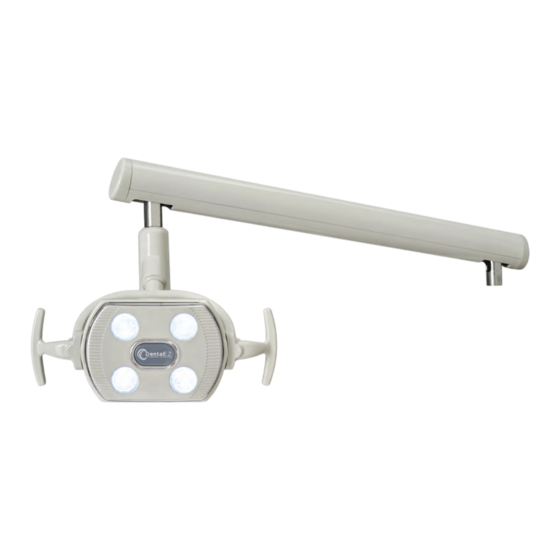
LEAVE THIS MANUAL IN THE DOCTOR’S OFFICE. ® Installation by an authorized DENTALEZ dealer service technician is recommended. NOTICE For any questions about an order, please contact a DENTALEZ Equipment customer service representative at 866-DTE-INFO. LIGHT ARM ASSEMBLY LIGHT BODY LED LIGHTS FIGURE 1. -
Page 5: Product Features
Three-axis adjustment allows for the widest range of positioning of the dental operatory light. Shadow-free illumination area lights the oral cavity. High- and low-intensity for optimum illumination. Aluminum casting light frame for better aesthetics and durability. Ergonomically designed T-handles for ease of movement. 866-DTE-INFO dentalez.com PN: 2717-271D... -
Page 6: Dimensions
SECTION I - INTRODUCTION DIMENSIONS TRACK MOUNT 24" 1⅜" 1¾" 4½" 9" 14⅜" 15" 15" FIGURE 2. LED LIGHT DIMENSIONS (TRACK MOUNT) CEILING MOUNT 1⅜" 24" 6½" 9" 31¼" 14⅜" 15" 15" FIGURE 3. LED LIGHT DIMENSIONS (CEILING MOUNT) -
Page 7: Range Of Motion
DIMENSIONS (CONTINUED) WALL/CABINET MOUNT 24" 1" 9" 4½" 1⅜" 56" 14⅜" 15" 15" FIGURE 4. LED LIGHT DIMENSIONS (WALL/CABINET MOUNT) RANGE OF MOTION 70° 70° 145° 45° 145° 135° FIGURE 5. LED LIGHT HEAD RANGE OF MOTION 866-DTE-INFO dentalez.com PN: 2717-271D... -
Page 8: Specifications
SECTION I - INTRODUCTION SPECIFICATIONS Power Supply (Primary) 100 240V AC, 50/60 Hz Power Supply (Secondary) Operating Amperage (Maximum) 115V - Two 1-Amp Slo-Blo Fuses 220V - Two .5-Amp Slo-Blo Track Mount: 86 (39) Unit Weight lbs (kg) Ceiling Mount: 40 (18) Wall/Cabinet Mount: 58 (26) Focal Length in (cm) 20 to 45 (50.8 to 114.3) -
Page 9: Classifications
= Do Not Place Box on Unlevel Surface give equipment reasonable protection against detrimental = Do Not Stack Box interference when operated in a commercial environment. 74ºC = Box Contents Safe Temperature Range (165ºF) -29ºC (-20ºF) = Box Contents Safe Humidity Range 866-DTE-INFO dentalez.com PN: 2717-271D... -
Page 10: Safety Precautions
To avoid the risk of electrical shock, this equipment must only be connected to a supply mains with protective earth. Do not modify this equipment without permission from DENTALEZ. Rating of main circuit breakers should be 20 Amps maximum. -
Page 11: Section Ii - Preinstallation
Carefully unpack the light. Inspect all of the items received to assure there has been no shipping damage. If damage is discovered, contact the carrier immediately; then report and file the appropriate claims with the carrier within 24 hours after delivery (see LIMITED WARRANTY). 866-DTE-INFO dentalez.com PN: 2717-271D... -
Page 12: Section Iii - Installation
SECTION III - INSTALLATION TRACK MOUNT ASSEMBLY NOTE: The ceiling structure must be capable of supporting 200 lbs. Additional bracing of the ceiling structure may need to be provided. The mounting lag bolts must go into a minimum of 2½" of solid wood. TOOLS NEEDED ... - Page 13 PALLET END CAP SUPPORT HUB TROLLEY TRANSFORMER TROLLEY COVER HOUSING COVER STOP COLLAR CUT END DROP POST MACHINED END SWIVEL KEY SWIVEL SLEEVE RIGID ARM SPINDLE LIGHT ARM ASSEMBLY FIGURE 8. EXPLODED VIEW OF TRACK LIGHT 866-DTE-INFO dentalez.com PN: 2717-271D...
- Page 14 SECTION III - INSTALLATION TRACK MOUNT ASSEMBLY (CONTINUED) 6. After loosening the end cap screws, take off the side covers and set them aside. Do not remove the end cap (Figure END CAP SCREWS (2) END CAP SIDE COVER FIGURE 9. LOOSEN (BUT DO NOT REMOVE) END CAP AND TAKE OFF SIDE COVERS Remove the four screws from the transformer housing cover, then take off the cover and set the screws and cover aside (Figure...
- Page 15 4. Tuck the wires in neatly and replace the transformer housing cover using the retaining screws previously removed. 5. Replace the side covers using the four Phillips-head screws previously removed. 6. Tighten the two Phillips-head screws on the loosened end cap. 866-DTE-INFO dentalez.com PN: 2717-271D...
- Page 16 SECTION III - INSTALLATION TRACK MOUNT ASSEMBLY (CONTINUED) DROP POST INSTALLATION NOTE: The track light is designed to accommodate up to a 10' ceiling. The drop post must be cut to length for ceiling height 8'6" and higher. Refer to the chart below for the correct post length for various ceiling heights. CEILING HEIGHT 8'-6"...
- Page 17 SECURE WITH THREE (3) BUTTON HEAD SCREWS FIGURE 15. SECURE SWIVEL SLEEVE AND DROP POST WITH THREE BUTTON HEAD SCREWS 14. Check the level of the post and readjust if necessary. 15. See TESTING section on the next page. 866-DTE-INFO dentalez.com PN: 2717-271D...
- Page 18 SECTION III - INSTALLATION TRACK MOUNT ASSEMBLY (CONTINUED) FLEX ARM HEIGHT ADJUSTMENT An adjustment can be made to the flex arm travel in the event the flex arm contacts the track or the ceiling. 2. To access the adjustable stop, remove the four screws that hold the arm cover. 3.
-
Page 19: Ceiling Mount Assembly
Ensure no lateral movement of the light column is possible. Check for an electrical circuit near the support area of the light. 25½" 25½" 6" 6" LEFT-HAND OPERATION RIGHT-HAND OPERATION FIGURE 17. SUGGESTED CEILING MOUNT LOCATIONS 866-DTE-INFO dentalez.com PN: 2717-271D... - Page 20 SECTION III - INSTALLATION CEILING MOUNT ASSEMBLY (CONTINUED) 3. Using the full-size ceiling mount template in the back of this manual, drill three holes for the ceiling mount plate. 4. Attach the ceiling mount plate to the framing joist using the provided 3/8" diameter lag screws with lock washers (FIGURE 18).
- Page 21 WIRING HOLE CEILING MOUNT PLATE JUNCTION BOX TRANSFORMER FIGURE 21. ROUTE POWER SUPPLY WIRING THROUGH HOLE IN CEILING MOUNT PLATE POWER SUPPLY GROUND JUNCTION BOX GROUND SCREW FIGURE 22. SECURE POWER SUPPLY WIRING TO JUNCTION BOX 866-DTE-INFO dentalez.com PN: 2717-271D...
- Page 22 SECTION III - INSTALLATION CEILING MOUNT ASSEMBLY (CONTINUED) DROP POST INSTALLATION NOTE: The ceiling light is designed to accommodate up to a 10' ceiling. The drop post must be cut to length for the appropriate ceiling height. Refer to the chart below for the correct post length for various ceiling heights. CEILING HEIGHT 8'-6"...
- Page 23 17. Pull the excess cord through the junction box and secure with strain relief bushing to the junction box (FIGURE 25). POWER SUPPLY GROUND JUNCTION BOX GROUND SCREW LIGHT CORD GROUND FIGURE 25. PULL CORD THROUGH JUNCTION BOX AND SECURE WITH STRAIN RELIEF BUSHING 866-DTE-INFO dentalez.com PN: 2717-271D...
- Page 24 SECTION III - INSTALLATION CEILING MOUNT ASSEMBLY (CONTINUED) 18. After the wiring connections are complete, replace the junction box cover. 19. Slide the cover and cover support up the drop post ans secure with set screws. 20. See TESTING section on this page. FLEX ARM HEIGHT ADJUSTMENT An adjustment can be made to the flex arm to limit the vertical travel of the arm.
-
Page 25: Wall Mount Assembly
From this point, swing a 60" radius arc (representing the long arm rotation) until an intersection with the wall is found. WALL WALL MOUNT R60° OPTIONAL RIGHT-HAND RIGHT-HAND OPERATION POSITION 66" OPTIONAL 25¼" LEFT-HAND LEFT-HAND OPERATION POSITION FLOOR WALL FIGURE 26. SUGGESTED WALL MOUNT LOCATION 866-DTE-INFO dentalez.com PN: 2717-271D... - Page 26 SECTION III - INSTALLATION WALL MOUNT ASSEMBLY (CONTINUED) WALL MOUNT INSTALLATION NOTE: Make sure the required power supply wiring runs from inside the wall to the proper location. After determining the proper position of the wall mount, use the wall mount template in the back of this manual to align mounting holes on two wall studs.
- Page 27 10. Secure the cover to the wall mount using the four screws previously removed. TESTING Before proceeding, make sure the power at the main circuit breaker panel is ON. 2. Move the toggle switch immediately behind the light head to turn the light ON. 866-DTE-INFO dentalez.com PN: 2717-271D...
-
Page 28: Cabinet Mount Assembly
NOT in contact with or interfering with any obstruction in the ceiling—especially sprinkler heads, smoke alarms, etc.! (FIGURE 29) gives the suggested mounting location for the DENTALEZ cabinet mount assembly and the HDX Intraoral X-ray. NOTE: The cabinet assembly will accommodate either one-light or two-light assemblies. - Page 29 UPPER PRIMARY ARM 2" ADJUSTABLE VERTICAL MOUNTING POST POST POST SUPPORT BRACKET LEVELING SCREWS BRACKET LEVELING SCREWS METAL ANGLE BRACKET PLYWOOD PANEL ELECTRICAL POWER CORD CABINET METAL FRAME END VIEW FIGURE 30. END VIEW FOR CABINET MOUNTING 866-DTE-INFO dentalez.com PN: 2717-271D...
- Page 30 SECTION III - INSTALLATION CABINET MOUNT ASSEMBLY (CONTINUED) 2. Attach the metal angle brackets supplied with the cabinet to the plywood center panel using the hardware supplied. NOTE: The location of the metal brackets at the lower end of the vertical mounting post(s) determines the height of the light assembly.
-
Page 31: Section Iv - Operation
2. To adjust brightness levels, wave hand by sensor. Levels will adjust from low, to medium, then high and back. TOGGLE LIGHT SWITCH SENSOR FIGURE 31. USE TOGGLE SWITCH TO TURN LIGHT ON OR OFF, OR HOLD HAND NEAR SENSOR 866-DTE-INFO dentalez.com PN: 2717-271D... -
Page 32: Positioning Light
SECTION IV - OPERATION POSITIONING LIGHT Using the handles on either side of the reflector head, position the light to illuminate the oral cavity (FIGURE 32). To take full advantage of the Simplicity LED Light's intensity and color correction, position the light NOTICE between 20"... -
Page 33: Eliminating Adjustable Arm Drift
Then slide off the top cover along with the end cap (FIGURE 35). 5/64" HEX SCREWS (2) END CAP ADJUSTABLE ARM TOP COVER FIGURE 35. REMOVE FOUR HEX SCREWS; SLIDE OFF TOP COVER AND END CAP 866-DTE-INFO dentalez.com PN: 2717-271D... - Page 34 SECTION IV - OPERATION ELIMINATING ADJUSTABLE ARM DRIFT (CONTINUED) 3. Insert a 9/64" hex key into the two small holes in the side of the adjustable arm and completely loosen the friction block (FIGURE 36). 9/64" HEX KEY FRICTION BLOCK ADJUSTABLE ARM SMALL HOLES (2) FIGURE 36.
-
Page 35: Section V - Care & Maintenance
The following disinfectants are acceptable to use: CaviCide CaviWipes ® Banicide ® BactSpray ® CaviCide and CaviWipes are trademarks of Metrex Research, LLC. Banicide is a registered trademark of Pascal Company., Inc. BactSpray ANVISA Registration No.: 3207900410015 866-DTE-INFO dentalez.com PN: 2717-271D... -
Page 36: Section Vi - User Service Information
The DENTALEZ technical service department is available to supply personnel with any additional information or instructions needed to repair or maintain the dental light. The following chart should be used when troubleshooting light problems. If these suggested troubleshooting... -
Page 37: Service Instruction
LED DENTAL LIGHT INFORMATION SERVICE INSTRUCTION DISPOSAL OF EQUIPMENT If the area of concern is not addressed in this manual, DISPOSAL AND DECOMMISSIONING OF contact DENTALEZ customer service at 866-DTE-INFO. DENTALEZ PRODUCTS (See LIMITED WARRANTY.) NOTE: All local regulatory requirements for disposal Please have the following product information available. -
Page 38: Section Vii - Parts List
SECTION VII - PARTS LIST REPLACEMENT PARTS LIGHT HEAD ASSEMBLY Part/Kit Name Part/Kit No. Light Head 3802-581 Handle 3802-609 Switch Assembly 3802-351 TRANSFORMER Part/Kit Name Part/Kit No. Transformer 3801-804 Fuse Kit, 115V 3802-252 Fuse Kit, 220V 3802-253... - Page 39 SECTION VII - PARTS LIST SIMPLICITY LED DENTAL LIGHT REPLACEMENT PARTS Part/Kit Name Part/Kit No. LIGHT ARM Arm End Cap 3801-811 Rigid Arm Cap 3801-814 Post Bushing 3801-848 866-DTE-INFO dentalez.com PN: 2717-271D...
- Page 40 SECTION VII - PARTS LIST REPLACEMENT PARTS TRACK ASSEMBLY Part/Kit Name Part/Kit No. Fuse Kit, 115V 3802-252 Fuse Kit, 220V 3802-253 Trolley Wheels 3802-243 Trolley Brake 3658-406 Transformer 3801-804 Set Screw 1625-093 Collar, Ceiling Stop 2673-047 Swivel, Sleeve & Key 3801-310 Drop Post, 8 ft 2586-118...
- Page 41 Part/Kit No. CEILING MOUNT Transformer 3801-804 Fuse Kit, 115V 3802-252 Fuse Kit, 220V 3802-253 Set Screw 1625-093 Collar, Ceiling Stop 2673-047 Drop Post, 8 ft 2586-118 Drop Post, 10 ft 2586-119 Swivel, Sleeve & Key 3801-310 866-DTE-INFO dentalez.com PN: 2717-271D...
-
Page 42: Wiring Schematic
WIRING SCHEMATIC... -
Page 43: Emc Information
Hz) Magnetic Field IEC 3 A/m 3 A/m levels characteristic of a typical location in a 61000-4-8 typical commercial or hospital environment. NOTE: Ut is the AC mains voltage prior to application of the test level. 866-DTE-INFO dentalez.com PN: 2717-271D... - Page 44 EMC INFORMATION GUIDANCE AND MANUFACTURER’S DECLARATION – ELECTROMAGNETIC IMMUNITY ALL ME EQUIPMENT AND ME SYSTEMS The light is intended for use in the electromagnetic environment specified below. The customer or the user of the light should assure that it is used in such an environment.
- Page 45 SIMPLICITY LED DENTAL LIGHT NOTES: 866-DTE-INFO dentalez.com PN: 2717-271D...
-
Page 46: Limited Warranty
We are not responsible for shipping damages. We will, however, help you file a claim with the freight carrier. Written repair estimates are available. DENTALEZ warrants all equipment and parts to be free of defects in material and workmanship, under normal usage under the following terms:... -
Page 47: Privacy Policy
Effective Date: November 1, 2023. Introduction and Overview. This Privacy Policy describes how DentalEZ, Inc. its subsidiaries and affiliates (collectively “DentalEZ,” “we,” “our,” or “us”) collects, uses, and shares information about you as well as your rights and choices. This Privacy Policy applies to your use of the DentalEZ equipment containing the Aeras platform, or similar “smart technology”... - Page 48 Equipment Usage and Performance Data, including performance data collected from sensors connected to the DentalEZ smart technology in your dental or medical equipment, including by not limited to when the equipment is used and for how long, what equipment functions are being used, how the equipment is running, power surges, tank pressure, voltage, oil or water level, maintenance alert, service history, pump intake, runtime and vacuum efficiency, and other kinds of equipment performance data.
- Page 49 We also share information in accordance with the applicable laws in order to protect the rights, property, life, health, security and safety of DentalEZ, DentalEZ personnel, the Service or any third party.
- Page 50 “Contact Us” section below with the word UNSUBSCRIBE in the subject field of the email. Please note that you cannot optout of non-promotional emails, such as those about your account, transactions, servicing, or DentalEZ’s ongoing business relations. •...
- Page 51 The Service is intended for a general audience and not directed to children under eighteen (18) years of age. DentalEZ does not knowingly collect personal information of children under the age of thirteen (13). If you are a parent or guardian and believe DentalEZ has collected such information in a manner not permitted by law, please contact us as set out in the “Contact Us”...
-
Page 52: Terms Of Use
These Terms of Use (“Online Terms”) set forth a legally binding agreement between DENTALEZ, Inc., DentalEZ Alabama, Inc., DTE Oregon, Inc., their subsidiaries and affiliates (collectively “DentalEZ” , “we” , “our” , or “us”) and the person or entity identified on the order form or other Service (as defined below) subscription purchase document (“Customer”). - Page 53 Availability. DentalEZ may suspend or terminate the availability of the Service and Content, in whole or in part, to any Account, individual user or all users, for any reason (including, a failure to pay Service subscription fees when due), in DentalEZ’...
- Page 54 In the event of any errors relating to the pricing or specifications, DentalEZ shall have the right to refuse or cancel any orders in its sole discretion. If we charged your credit card or other Account prior to our cancellation, we will issue a credit to your Account in the amount of the charge.
- Page 55 (whether express or implied) or other obligations with respect to Service hereunder. DentalEZ has no obligation to monitor or maintain Other Services and may disable or restrict access to any Other Services at any time without notice.
- Page 56 DentalEZIOT@ DentalEZ.com and specifying you want to opt-out of calls. For text messages, you can also text “HELP” at any time for more information. We will unsubscribe your phone number from reoccurring texts messages from us within 10 business days of our receipt of your opt-out request.
- Page 57 D. Authority of Arbitrator. The arbitrator will decide the rights and liabilities, if any, of you and DentalEZ, and the dispute will not be consolidated with any other matters or joined with any other cases or parties. The arbitrator shall have the authority to grant motions dispositive of all or part of any claim.
- Page 58 You agree to cooperate with DentalEZ’ defense of any claim. You will not in any event settle any claim without the prior written consent of DentalEZ. This provision does not require you to indemnify us for any unconscionable commercial practice by us or for our fraud, deception, false promise, misrepresentation or concealment, suppression or omission of any material fact in connection with the Service.
- Page 59 The summaries of provisions and section headings are provided for convenience only and shall not limit the full Terms. DentalEZ may assign its rights and obligations under the Terms, in whole or in part, to any party at any time without any notice. The Terms may not be assigned by you, and you may not delegate your duties under them, without the prior written consent of an officer of DentalEZ.
- Page 60 Service. Except as expressly set forth in the Terms, (i) no failure or delay by you or DentalEZ in exercising any of rights, powers, or remedies under will operate as a waiver of that or any other right, power, or remedy, and (ii) no waiver or modification of any term of the will be effective unless in writing and signed by the party against whom the waiver or modification is sought to be enforced.
- Page 61 DENTALEZ Alabama, Inc. 2500 Highway 31 South Bay Minette, AL 36507 T: 866-DTE-INFO DENTALEZ.COM © 2024 DENTALEZ, Inc. DENTALEZ is a registered trademark. PN: 2717-271D April, 2024 Printed in USA...
Need help?
Do you have a question about the Heritage Simplicity and is the answer not in the manual?
Questions and answers