Table of Contents
Advertisement
Quick Links
Advertisement
Table of Contents

Related Manuals for DentalEZ Heritage CORE Chair


Summary of Contents for DentalEZ Heritage CORE Chair
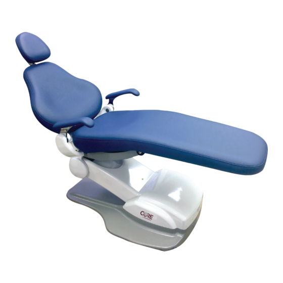
- Page 1 CORE CHAIR USER MANUAL...
-
Page 2: Table Of Contents
TABLE OF CONTENTS SECTION I - INTRODUCTION Product Overview ..........................1 Product Features..........................2 Dimensions ............................3 Range of Motion ..........................4 Specifications............................5 Recommended Environmental Conditions ..................5 Classifications ............................. 6 Explanation of Symbols & Signs ......................6 Safety Precautions ..........................7 SECTION II - PREINSTALLATION Packaging ............................ - Page 3 CHAIR SECTION VI - USER SERVICE INFORMATION Service Instruction ..........................38 Disposal of Equipment ........................38 SECTION VII - PARTS LIST Replacement Parts ........................... 39 DENTALEZ Parts Online ........................39 EMC INFORMATION ........................... 40 LIMITED WARRANTY .......................... 43 866-DTE-INFO dentalez.com...
-
Page 4: Section I - Introduction
After the chair is installed, review the features, operation procedures, and care guidelines with the doctor’s staff. LEAVE THIS MANUAL IN THE DOCTOR’S OFFICE. ® Installation by an authorized DENTALEZ dealer service technician is recommended. NOTICE For any questions about an order, please contact a DENTALEZ Equipment customer service representative at 866-DTE-INFO. HEADREST BACK ARMREST SEAT... -
Page 5: Product Features
Double articulating headrest. Base safety switch feature ensures nothing gets caught underneath the base as it lowers. OPTIONAL FEATURES Wired foot control provides programmable preset positioning. Touchpad control provides easy and rapid patient positioning. 866-DTE-INFO dentalez.com PN: 2717-268C... -
Page 6: Dimensions
SECTION I - INTRODUCTION DIMENSIONS 74" TOP RECLINING 8⅝" 20" 19¾" 26⅜" 25⅝" 9⅞" 20⅜" 27⅞" 18⅛" SIDE RECLINING 19⅝" 17⅞" 16⅛" 15" 11" 39¾" SIDE UPRIGHT 57" 48¾" 29½" 26⅜" 17" FIGURE 2. DENTAL CHAIR DIMENSIONS... -
Page 7: Range Of Motion
SECTION I - INTRODUCTION CORE CHAIR RANGE OF MOTION 15° 15° FIGURE 3. DENTAL CHAIR RANGE OF MOTION 866-DTE-INFO dentalez.com PN: 2717-268C... -
Page 8: Specifications
SECTION I - INTRODUCTION SPECIFICATIONS 115V 220V Voltage (AC) 115, 60 Hz, as applicable 220, 50/60 Hz, as applicable Control Voltage (AC) 5V DC F1/F2 - 10A, F3 - 100 mA Fuses (Type M) F1/F2 - 6.3A, F3 - 63 mA Shipping (Package) Weight (lbs) Chair: 396.9 (180 kg) Empty Weight (lbs) -
Page 9: Classifications
= Do Not Trash = Box Must Remain Upright = Do Not Place Box on Unlevel Surface = Do Not Stack Box 74ºC = Box Contents Safe Temperature Range (165ºF) -29ºC (-20ºF) = Box Contents Safe Humidity Range 866-DTE-INFO dentalez.com PN: 2717-268C... -
Page 10: Safety Precautions
The plug cannot be located in a position that requires tools to access. Do not modify the chair without permission from DENTALEZ. The use of ACCESSORY equipment not complying with the equivalent safety requirements of this equipment may lead to a reduced level of safety of the resulting system. Consideration relating to the choice shall include: ... -
Page 11: Section Ii - Preinstallation
2. Remove the outer strapping and plastic, then remove the screws from the cardboard box, one (1) from each side and two (2) from each end. 3. Remove the outer box top and set aside. 4. Remove the cardboard supports. 5. Remove all the plastic wrapping and foam. 866-DTE-INFO dentalez.com PN: 2717-268C... - Page 12 SECTION II - PREINSTALLATION PACKAGING (CONTINUED) 6. Use wire cutters to cut the support straps/zip ties located on both sides of the chair. Two (2) ties at either side secure the chair to the pallet. The other ties secure the chair to itself (FIGURE SUPPORT STRAPS/...
- Page 13 Upholstered Back Assembly Upholstered Seat Upholstered Armrests Headrest Hardware Package Any Additional Ordered Options UPHOLSTERED BACK ASSEMBLY UPHOLSTERED SEAT CHAIR CONTROLS HEADREST OPTIONS HARDWARE PACKAGE UPHOLSTERED ARMRESTS FIGURE 7. CHAIR UPHOLSTERY PACKAGING 866-DTE-INFO dentalez.com PN: 2717-268C...
-
Page 14: Chair Placement
SECTION II - PREINSTALLATION CHAIR PLACEMENT To prevent injury as a result of chair tipping, chair must be placed on a smooth, hard and level WARNING floor. DO NOT position the chair any place where it would interfere with unplugging the chair power cord. -
Page 15: Section Iii - Installation
4. Apply medium-strength threadlocker to the set screw located on the end of the backrest. 5. Using a 3/32" hex key, tighten the set screw against the flat surface of the pin to hold the internal arm. 866-DTE-INFO dentalez.com PN: 2717-268C... -
Page 16: Seat Frame
SECTION III - INSTALLATION SEAT FRAME TOOLS REQUIRED Phillips-head Screwdriver ASSEMBLE SEAT FRAME Remove the five (5) Phillips-head screws that hold the seat upholstery to the seat frame. Remove the seat upholstery. Retain screws for installation (FIGURE 10). SEAT FRAME SCREWS (5) FIGURE 10. - Page 17 Replace cotter pin to hold frame in place (FIGURE 12) NYLON WASHERS SEAT FRAME CHAIR BASE COTTER PIN CLEVIS PIN FIGURE 12. CLEVIS PIN WITH INSERTED COTTER PIN 866-DTE-INFO dentalez.com PN: 2717-268C...
-
Page 18: Foot Control
SECTION III - INSTALLATION FOOT CONTROL To prevent any chance of electrical shock, always disconnect power when indicated. WARNING TOOLS REQUIRED 1/8" Hex Key CONNECT FOOT CONTROL 1. Disconnect the chair power. 2. Using a 1/8" hex key, remove the screws (2) on the sides of the pump cover, then take the cover off and set it aside (FIGURE 13). - Page 19 4. Connect the wire plug of the foot control into the control board (FIGURE 15). WIRE PLUG FIGURE 15. CONNECT WIRE PLUG OF FOOT CONTROL TO CONTROL BOARD 5. Reconnect the chair power and test the foot control for proper function. 6. Reinstall the chair pump cover. 866-DTE-INFO dentalez.com PN: 2717-268C...
-
Page 20: Touchpad Control
SECTION III - INSTALLATION TOUCHPAD CONTROL To prevent any chance of electrical shock, always disconnect power when indicated. WARNING TOOLS REQUIRED 13 mm Wrench 1/8" Hex Key CONNECT TOUCHPAD CONTROL 1. Disconnect the chair power. 2. Locate bracket holes on the underside of the armrest support (FIGURE 16). - Page 21 5. Connect the wire plug of the touchpad into the supplied extension, then plug the extension into the control board (FIGURE 19). CONTROL BOARD WIRE PLUG FIGURE 19. CONNECT WIRE PLUG OF TOUCHPAD TO CONTROL BOARD 6. Reconnect the chair power and test the touchpad for proper function. Reinstall the chair pump cover. 866-DTE-INFO dentalez.com PN: 2717-268C...
-
Page 22: Seat Upholstery
SECTION III - INSTALLATION SEAT UPHOLSTERY If the chair is part of an operatory, wait until entire installation is complete before installing CAUTION upholstery. Failure to do so may result in damage to the upholstery. TOOLS REQUIRED Phillips-head Screwdriver ASSEMBLE SEAT UPHOLSTERY Align the studs located on the underside of the upholstered seat with the holes in the seat frame. -
Page 23: Headrest
2. Tighten the tension adjustment screws as necessary until the desired slide tension is reached (FIGURE 21). CHAIR BACK CASTING TENSION ADJUSTMENT SCREWS (6) BLADE FIGURE 21. SLIDE BLADE OF HEADREST INTO OPENING AND TIGHTEN TENSION ADJUSTMENT SCREWS 866-DTE-INFO dentalez.com PN: 2717-268C... -
Page 24: Back Upholstery
SECTION III - INSTALLATION BACK UPHOLSTERY ASSEMBLE BACK UPHOLSTERY Align the two upper and two lower T-bolt studs on the chair back casting with the slide holes on the back of the upholstered chair back. 2. Firmly press the upholstered chair back over the T-bolt studs and slide the upholstered chair back down until all four (4) T-bolt studs are locked into place (FIGURE 22). -
Page 25: Armrests
2. From the underside of each arm, using two (2) 5/32" hex screws, attach each upholstered arm to the arm supports (FIGURE 23). UPHOLSTERED ARM SUPPORT ARMREST FIGURE 23. ATTACH ARM TO ARM SUPPORT WITH HEX SCREWS 866-DTE-INFO dentalez.com PN: 2717-268C... -
Page 26: Installation Checklist
Do all chair functions operate smoothly and quietly? Do the armrests lock into position? Answering NO to any of these questions is the result of improper installation or a product malfunction. After ensuring all connections, call DENTALEZ technical service at 866-DTE-INFO. -
Page 27: Delivery Units
Installation of the console mounted delivery unit Magellan style delivery unit is recommended before upholstery installation. Install delivery units according to the manufacturer's instructions supplied with the delivery unit. CONSOLE MOUNTED DELIVERY UNIT MAGELLAN STYLE DELIVERY UNIT 866-DTE-INFO dentalez.com PN: 2717-268C... -
Page 28: Section Iv - Operation
SECTION IV - OPERATION BASE LOWERING SAFETY SWITCH The chair is equipped with a base lowering safety switch. This feature ensures nothing gets caught underneath the chair base as it is lowered. The following describes how this feature operates: When the base cantilever section is lowered and contacts an obstruction, the cover on the underside of the cantilever section will move upward and activate the chair safety switches. -
Page 29: Armrests
Pull up the arm lock trigger located under the lower arm assembly and lower the armrest (FIGURE 25). 2. Lift up the lower end of the armrest until the armrest stops and clicks, locking the armrest into position. ARM LOCK TRIGGER FIGURE 25. PULL UP ARM LOCK TRIGGER AND LOWER ARMREST 866-DTE-INFO dentalez.com PN: 2717-268C... -
Page 30: Double Articulating Headrest
SECTION IV - OPERATION DOUBLE ARTICULATING HEADREST To position the headrest height, firmly push down or pull up the blade from the chair back to change the headrest height. To position the headrest tilt: While facing the back of the headrest, fully depress the release mechanism on the right. 2. -
Page 31: Manual Chair Positioning
AUTO BUTTONS 1, 2, 3 & 4 BACK BACK UP DOWN BUTTON BUTTON BASE DOWN BASE BUTTON BACK BACK DOWN AUTO BASE BUTTONS DOWN 1, 2, 3 & 4 FIGURE 27. CHAIR TOUCHPAD CONTROL AND FOOT CONTROL 866-DTE-INFO dentalez.com PN: 2717-268C... -
Page 32: Automatic Chair Positioning
SECTION IV - OPERATION AUTOMATIC CHAIR POSITIONING VIEW ONLINE INSTRUCTIONS Scan QR code for video instructions on chair automatic positioning. PROGRAMMING AUTO POSITIONS To establish an auto preset position, perform the following steps: Using the touchpad control, follow the direction of the arrow to maneuver the chair to the desired position (FIGURE 28). - Page 33 REPROGRAMMING AUTO POSITIONS To change a programmed position, simply maneuver the chair to the desired position and follow the PROGRAMMING AUTO POSITIONS instructions described in this section. NOTE: Reprogramming a new auto position erases the old position. 866-DTE-INFO dentalez.com PN: 2717-268C...
-
Page 34: Programming Chair Travel Limits
SECTION IV - OPERATION PROGRAMMING CHAIR TRAVEL LIMITS VIEW ONLINE INSTRUCTIONS Scan QR code for video instructions on chair automatic positioning. TOOLS REQUIRED 1/8" Hex Key Tape Measure PROGRAMMING USING TOUCHPAD CONTROL Use 1/8" hex key to remove the screws (2) on the sides of the pump cover. Retain the screws. Take the cover off and set it aside (FIGURE 30). - Page 35 (memory) button located at the rear of the chair, use the foot control to make sure the base is moved all the way down and the chair back is all the way down (FIGURE 33). MEMORY BUTTON FIGURE 33. HOLD DOWN M (MEMORY) BUTTON AND MOVE CHAIR BASE AND BACK DOWN 866-DTE-INFO dentalez.com PN: 2717-268C...
- Page 36 SECTION IV - OPERATION PROGRAMMING CHAIR TRAVEL LIMITS (CONTINUED) 5. Set chair base up. 6. Set chair base down. a. While holding down the (memory) button, run a. While holding down the (memory) button, run the chair base all the way up, then come down until the chair base all the way down, then come up 22"...
- Page 37 9. Programming the chair is now complete. Place the 1 and 2 DIP switches back into the original position. FIGURE 36. SETTING CORE CHAIR BACK UP 10. Reattach the light harness and reinstall the pump cover using two (2) retained hex screws. 866-DTE-INFO dentalez.com PN: 2717-268C...
-
Page 38: Section V - Care & Maintenance
SECTION V - CARE & MAINTENANCE CLEANING OVERVIEW Improper cleaning and disinfection techniques could lead to cross-contamination; therefore, prior WARNING to each use, properly clean and disinfect the chair’s exterior in accordance with normal dental procedures. Pay strict attention to all of the cleaning product manufacturer’s warnings and cautions. CAUTION ... - Page 39 Formula 409 is a registered trademark of the Clorox Company. Fantastik Spray Cleaner is a registered trademark of the Texize Division of Dow Products, Inc. METAL SURFACES AND CHROME PARTS For ordinary dirt, fingerprints, etc., use a non-abrasive, all-purpose cleaner. 866-DTE-INFO dentalez.com PN: 2717-268C...
-
Page 40: Disinfecting
SECTION V - CARE & MAINTENANCE DISINFECTING UPHOLSTERY The chair's upholstery is comprised of material from the following manufacturers: ® ® Naugahyde Beauty Gard from Uniroyal Naugahyde brand fabrics, Spirit II and Neochrome II with Advanced Beauty Gard contains an agent to protect it against bacterial and fungal microorganisms. -
Page 41: Section Vi - User Service Information
CHAIR INFORMATION SERVICE INSTRUCTION DISPOSAL OF EQUIPMENT If the area of concern is not addressed in this manual, DISPOSAL AND DECOMMISSIONING OF contact DENTALEZ customer service at 866-DTE-INFO. DENTALEZ PRODUCTS (See LIMITED WARRANTY.) NOTE: All local regulatory requirements for disposal Please have the following product information available. -
Page 42: Section Vii - Parts List
Master Circuit Board (220V AC) 3802-587 Base Potentiometer to PCB Harness 3802-590 Potentiometer Display Board 3802-610 CONTROLS Part/Kit Name Part/Kit No. Foot Control 3613-127 Touchpad Control 3802-264 DENTALEZ PARTS ONLINE To view parts online, visit DENTALEZPARTS.COM or scan QR code with a smart phone. -
Page 43: Emc Information
Hz) Magnetic Field IEC 3 A/m 3 A/m levels characteristic of a typical location in a 61000-4-8 typical commercial or hospital environment. NOTE: Ut is the AC mains voltage prior to application of the test level. 866-DTE-INFO dentalez.com PN: 2717-268C... - Page 44 EMC INFORMATION GUIDANCE AND MANUFACTURER’S DECLARATION – ELECTROMAGNETIC IMMUNITY ALL ME EQUIPMENT AND ME SYSTEMS The chair is intended for use in the electromagnetic environment specified below. The customer or the user of the chair should assure that it is used in such an environment.
- Page 45 CORE CHAIR NOTES: 866-DTE-INFO dentalez.com PN: 2717-268C...
-
Page 46: Limited Warranty
CHAIR DENTALEZ and its employees are proud of the products we provide to the dental community. We stand behind these products with a warranty against defects in material and workmanship as provided below and have our own in-house repair facility to service our products. - Page 47 DENTALEZ Alabama, Inc. 2500 Highway 31 South Bay Minette, AL 36507 T: 866-DTE-INFO DENTALEZ.COM © 2021 DENTALEZ, Inc. DENTALEZ is a registered trademark. PN: 2717-268C July, 2021 Printed in USA...
Need help?
Do you have a question about the Heritage CORE Chair and is the answer not in the manual?
Questions and answers