Table of Contents
Advertisement
Advertisement
Table of Contents

Related Manuals for DentalEZ J-Chair J-3


Summary of Contents for DentalEZ J-Chair J-3
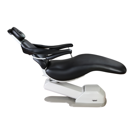
- Page 1 ® (Model J-3)
-
Page 2: Table Of Contents
Table of Contents Section I Introduction Specifications .......................... 3 Classifications ......................... 3 Dimensions ..........................4 Warnings / Cautions / Notices ................... 4 Section II Pre-installation Unpacking ..........................5 Chair Transport and Placement ..................6 Section III Installation Preparing Chair ........................ 7-10 Delivery Units ........................ -
Page 3: Section I Introduction
Their head should be on the headrest with The DentalEZ J-Chair is designed to provide trou- their feet at the toe of the chair. Their arms should be ble-free service when installed, operated and cared for on the armrests or folded across their midsection. -
Page 4: Specifications
Mode of operation: Duty cycle: 1 min. ON, 6 min. OFF equipment can affect medical electrical equipment. The authorized European representative is: DentalEZ (GB) Ltd., Cleveland Way, Hemel Hempstead, Hertfordshire, HP2 7DY, England Phone: (01442) 269301 Attn: Mr. Jeff Whitehouse J-Chair ®... -
Page 5: Dimensions
Rating of main circuit breakers should be 20 Amp requires tools to access. maximum. NOTICE WARNING Isolating the unit from the supply mains is accomplished Do not modify the J/V-Generation Chair without by unplugging the unit from the power receptacle. permission from DentalEZ. Installation, Operation and Care Manual... -
Page 6: Section Ii Pre-Installation
DO NOT REMOVE Hardware this strap until the chair is out of the carton and in its Package position on the floor. Upholstered Armrests NOTICE For any questions about an order, please contact a DentalEZ Equipment customer service representative at 1-866-DTE-INFO. J-Chair ®... -
Page 7: Chair Transport And Placement
Section II Pre-installation J-Chair ® WARNING Chair Transport and Placement Before mounting a delivery unit, it is recommended to anchor the chair to the floor for optimal stability. WARNING During transportation, the chair must be at its lowest height and all attachments must be secured in their lowest and most central positions possible. Failure to comply may result in injury and/or damage to Anchor equipment. -
Page 8: Section Iii Installation
3. On one side of the chair back, press the NOTICE switch with the up arrow between the 3 and 4 buttons to raise the chair’s base to its full up Installation by an authorized DentalEZ dealer service technician is recommended. position. NOTICE Wiring schematics are provided with this manual. - Page 9 J-Chair Section III Installation ® 2. Remove the decorative plastic cap that covers the hole on the opposite side of where the drive arm goes into the seat mount casting. 3. Flip the floating arm all the way up. Rubber Shipping Plug Floating Arm...
- Page 10 Section III Installation 7. Using a 5/32" Allen wrench, remove the 11. Rotate the drive arm up, and make sure it will shoulder screw, bushing and washer that holds not pull out. the driven arm to the drive arm. 12. Rotate the two armrests until the hole in the driven arm lines up with the threaded hole in the drive arm.
-
Page 11: Delivery Units
Section III Installation J-Chair ® auxiliary controller is added, the DIP switch settings on the main control board will need to be set before Control Sleeve the controller is recognized. (See the DIP Switch Settings, Page 25.) Floating Auxiliary Controller Options 5/16"... - Page 12 Section III Installation 1. Raise the seat to its full UP position. CAUTION 2. Disconnect the chair power. To prevent air caster damage, DO NOT EXCEED 3. Feed the light receptacle cord through the slot 138 kPa (20 PSI). If bouncing should occur, reduce the air pressure as required.
- Page 13 • The 220 VAC relay is used with a light that requires a 220 VAC (single phase) connection to its transformer. • The 24 VAC relay is used with a DentalEZ Simplicity Operatory Light and power Auxiliary ® Light Relay module package.
-
Page 14: Chair Upholstery
Section III Installation 9. After a light has been installed and set to the ON position, do the following to check the operation of the auxiliary light relay: a. Depress the auxiliary light relay button once on the touch pad control. (Pressing the auxiliary light relay button toggles the on/off state of the light.) Wire... - Page 15 Section III Installation J-Chair ® 5. Using a 1/4-20 x 5/8" screw, fasten the upper Arm Slings end of the arm sling's larger tab to the chair For each arm sling, perform the following steps: back casting, allowing the sling to drape over the upholstered arm rest.
- Page 16 Section III Installation Arm Cover Plate 1. While keeping the lower part of the back upholstery slightly lifted, align the two holes 1. Under each arm, position the arm cover plates in the top of the back upholstery over the two with the straight end of the plate towards the washers at the top of the chair back casting.
- Page 17 Section III Installation J-Chair ® Seat Cushion Head Rest Place the magnetic headrest cushion or magnetic neck 1. Place the seat cushion on the seat mount support on the J-Chair. casting. 2. Slide decorator plastic covered caps on four WARNING 1/4-20 x 5/8"...
-
Page 18: Section Iv Operation
Section IV Operation Manual Positioning Automatic Positioning Programming Auto Positions Manual positioning of the J-Chair is accomplished by using the back switch controls located on each The J-Chair back switch controls, the foot control side of the chair, the foot control or the unit touch and unit touch pad control are capable of execut- pad control. - Page 19 Section IV Operation J-Chair ® Unit Touch Pad Control Foot Control Operator A/B Auto Buttons Back Up Seat Up Base Up Back Seat Down Down Seat Up Base Base Up Down Auxiliary Light Toggle Relay Button A LED B LED Light Light Light...
-
Page 20: Controller Functions/Modes
Section IV Operation Activating Auto Positions Command Time-out When a function is moved or an auto position is ac- To activate the auto positions: tivated, the chair assumes movement completion will 1. Determine A or B user by depressing the take no longer than 45 seconds. -
Page 21: Standard Features
Section IV Operation J-Chair ® 2. Swivel the chair to the desired position. Standard Features 3. Lock the chair brake by moving the brake handle to the right. Base Lowering Safety The following describes how this feature operates: Optional Features 1. - Page 22 Section IV Operation Auxiliary Light Relay Surgical Sling Make sure the surgical sling board is properly seated The auxiliary light relay allows the operator to turn in the pouch located on the underside of the surgical on an attached light and then control its on/off state sling.
-
Page 23: Section V Care
Section V Care J-Chair ® b. Apply the above solution to the Cleaning upholstery using a soft, damp cloth. NOTE: If necessary, a soft bristle brush may WARNING be used. c. Using a soft cloth dampened in plain Improper cleaning and disinfection techniques could lead to cross-contamination. -
Page 24: Disinfecting
Section V Care Plastic and Coated Metal Surfaces Bacterial Species: • Bacillus Subtilis CAUTION • Staphylococcus Aureus • Aerobacter Aerogenes ● NEVER use abrasives or petroleum-based • Proteus Vulgaris cleaners on any plastic or coated metal surfaces • Brevibacterium Species unless otherwise specified. -
Page 25: Section Vi User Service Information
Section VI User Service Information J-Chair ® DIP Switch Settings Main Control Board A DIP switch assembly, which is located at the top center of the main control board under the base #1 DIP cover, is used to set certain functions of the chair's Switch electronic control package. - Page 26 Section VI User Service Information BEEP CODE CONDITION ACTION Constant Fast Special Installation Mode (base Disconnect the chair power. Move #1 DIP switch to ON. Beep (FB) automatically rises) Reconnect the chair power. Constant Short Base lower safety cover contacted Move the base up and remove obstruction under cover.
-
Page 27: Led Codes
Special Installation (base automatically rises) Service Instruction Model/Serial If the area of concern is not addressed in this man- Number ual, contact your local DentalEZ full-service dealer- Label ship. Please have the following product information available: • Model Name: • Model Number: (found on the front of the seat mount casting ) •... -
Page 28: Led Codes
Section VI User Service Information LED CODE CONDITION ACTION Special installation mode Disconnect the chair power. Move #1 DIP switch to ON. Reconnect the chair power. A/D converter failure Replace the chair main control board. ● ● ● EEPROM failure Replace the chair main control board. -
Page 29: Programming Travel Limits
J-Chair Section VI User Service Information ® NOTE: The upper and lower travel limit values Programming Travel Limits specified are factory settings. Values within the ranges are valid depending on specific applications. Different Tools Required: travel limit values may be required to achieve adequate •... - Page 30 Section VI User Service Information d. Press and release the auto #1 button on a b. Move the back down until the distance control. between the end of the spring connecting link and the rear edge of the seat mount CAUTION casting rib measures between 11"...
-
Page 31: Control Valve Speed Adjustment
Section VI User Service Information J-Chair ® WARNING Control Valve Speed Adjustment WEAR SAFETY GLASSES while Tools Required: adjusting the valve. Flow control valves should not be turned out • Phillips Screwdriver farther than the top of their heads • Flat-head Screwdriver being even with the valve body surface. -
Page 32: Disposal Of Equipment
(clockwise). Disposal and Decommissioning of NOTE: With the flow adjustments closed all the DentalEZ products: way, the seat may not move at all until the valve is Note: All local regulatory requirements adjusted open a little. for disposal and decommissioning of e. -
Page 33: Section Vii Parts Lists (General)
Section VII Parts Lists (General) J-Chair ® Controls Hydraulic Part/Kit Name Part/Kit No. Part/Kit Name Part/Kit No. J-3 Right Back Switch 3801-894 Pump (115 VAC) 3801-774 Pump (220 VAC) 3801-775 J-3 Left Back Switch 3801-895 Valve (115 VAC) 3801-776 Delivery Head Touchpad Option 3625-561 Valve (220 VAC) 3801-777... -
Page 34: Section Viii Parts Lists (W/Illustrations)
Section VIII Parts Lists (w/illustrations) Seat Cylinder Assembly Bracket Assembly, Cover Switch Back Cylinder Assembly Seat/Back Cylinder Assembly Part/Kit Name Part/Kit No. 1 Back/Seat Cylinder 3801-783 2 Back/Seat Potentiometer 3801-771 3 Safety Limit Switch 3801-431 4 Potentiometer Actuator 3801-773 5 Vent Line & Fittings 3802-110 J-Chair ®... -
Page 35: Covers
Section VIII Parts Lists (w/illustrations) J-Chair ® Covers Part/Kit Name Part/Kit No. 1 Pump Cover 3801-737 2 Lower Cantilever Cover 3801-756 3 Upper Cantilever Cover 3801-787 4 Brake Cover 3801755 5 Main Extension Spring 3801-445 6 Front Cover Assembly 3801-793 7 Drive Arm 3801-748 Installation, Operation and Care Manual... -
Page 36: Back Assembly
Section VIII Parts Lists (w/illustrations) Back Assembly Part/Kit Name Part/Kit No. 1 Control Sleeve 3801-113 2 Right Arm 3801-747 3 Left Arm 3801-745 4 Arm Screw 3800-112 5 Back Control Cable 3801-853 6 Back & Foot Control, PCB 3801-763 7 Back Switch Wiring 3801-915 8 Right Back Switch 3801-894... -
Page 37: Hydraulic
Section VIII Parts Lists (w/illustrations) J-Chair ® Chassis Assembly 115 V Power Unit 125V 250V (Power cord wiring not shown for clarity.) 7 9 10 12 Hydraulic 1 3 4 6 Part/Kit Name Part/Kit No. 1 Hydraulic Valve (115 VAC) 3801-776 2 Solenoid Coil 3801-424... -
Page 38: Mechanical
Section VIII Parts Lists (w/illustrations) Bottom View (Base and cantilever mount not shown.) Mechanical Part/Kit Name Part/Kit No. 1 Brake Handle, 1/2" Shaft 3801-803 2 Lift Cylinder 3801-429 3 Potentiometer/Pinion Gear 3801-435 4 Tubing, Clear, 15', 1/4" 3801-418 5 Air Glide Regulator* 3801-791 6 Air Glide Toggle Valve* 3801-792... -
Page 39: Limited Warranty
DentalEZ Equipment Division -Chair (Model J-3) The DentalEZ Group and its employees are proud of the products we provide in the dental community. We stand behind these products with a warranty against defects in material and workmanship as provided below. -
Page 40: Emc Information
EMC Information WARNING ● Use only replacement cables listed in Parts Section. Other cables and accessories may negatively affect EMC performance. ● When the J-Chair is used adjacent to other equipment, observe the Chair to verify normal operation. Table 1 Guidance and manufacturer’s declaration - electromagnetic emissions The J-Chair (Model J-3) is intended for use in the electromagnetic environment specified below. - Page 41 EMC Information J-Chair ® Table 2 Guidance and manufacturer’s declaration – electromagnetic immunity The J- Chair (Model 3) is intended for use in the electromagnet environment specified below. The customer or the end user of the J-Chair should assure that it is used in such an environment. IEC 60601 Electromagnetic environment Immunity test...
- Page 42 EMC Information Table 4 Recommended separation distance between Portable and mobile RF communications equipment and the model @ 3Vrms The J-Chair (Model 3) is intended for use in an electromagnetic environment in which radiated RF disturbances are controlled. The customer or the user of the J-Chair can help prevent electromagnetic interference by maintaining a minimum distance between portable and mobile RF communications equipment (transmitters) and the J-Chair as recommended below, according to the maximum output power of the communications equipment.
-
Page 43: Emc Information
EMC Information J-Chair ® Table 6 Guidance and manufacturer’s declaration - electromagnetic emissions The J-Chai (Model 3) is intended for use in the electromagnetic environment specified below. The customer or the user of the J-Chair should assure that it is used in such an environment. Immunity test IEC 60601 Compliance... -
Page 44: Wiring Schematic
V-Chair V-Chair LEFT RIGHT SWITCH SWITCH Chair ® BACK SEAT Back Upper Seat Lower Seat Upper Back Seat Wiring Schematic Potentiometer Limit Switch Potentiometer Limit Switch Limit Switch (P2) (LS4) (P3) (LS6) (LS5) 1 2 3 1 2 3 BASE CANTILEVER Black Black Black... - Page 45 2500 Highway 31 South Bay Minette, Alabama 36507 1-866-DTE-INFO Fax: (251) 937-0461 www.dentalez.com © DentalEZ Alabama, Inc. Printed in USA PN: 2717-254B June, 2014...
Need help?
Do you have a question about the J-Chair J-3 and is the answer not in the manual?
Questions and answers