Table of Contents
Advertisement
Quick Links
®
BOCK
HG
Operating guide
HG22e/125-4
HG22e/125-4 S
HG22e/160-4
HG22e/160-4 S
HG22e/190-4
HG22e/190-4 S
HG34e/215-4
HG34e/215-4 S
HG34e/255-4 HG34e/255-4 S
HG34e/315-4
HG34e/315-4 S
HG34e/380-4 HG34e/380-4 S
Translation of the original instructions
22
e/HG 34 e
HGX22e/125-4 HGX22e/125-4 S
HGX22e/160-4 HGX22e/160-4 S
HGX22e/190-4 HGX22e/190-4 S
HG34e/215-4
HG34e/255-4 HGX34e/255-4 S
HG34e/315-4
HG34e/380-4 HGX34e/380-4 S
HGX34e/215-4 S
HGX34e/315-4 S
AQ451923867809en-000301
Advertisement
Table of Contents

Related Manuals for Danfoss BOCK HG22e


Summary of Contents for Danfoss BOCK HG22e
- Page 1 e/HG 34 e ® BOCK Operating guide HG22e/125-4 HG22e/125-4 S HGX22e/125-4 HGX22e/125-4 S HG22e/160-4 HG22e/160-4 S HGX22e/160-4 HGX22e/160-4 S HG22e/190-4 HG22e/190-4 S HGX22e/190-4 HGX22e/190-4 S HG34e/215-4 HG34e/215-4 S HG34e/215-4 HGX34e/215-4 S HG34e/255-4 HG34e/255-4 S HG34e/255-4 HGX34e/255-4 S HG34e/315-4 HG34e/315-4 S HG34e/315-4 HGX34e/315-4 S HG34e/380-4 HG34e/380-4 S HG34e/380-4 HGX34e/380-4 S Translation of the original instructions AQ451923867809en-000301...
- Page 2 Observe the safety instructions contained in these instructions. These instructions must be passed onto the end customer along with the unit in which the compres- sor is installed. 2 | AQ451923867809en-000301 © Danfoss | Climate Solutions | 2024.07...
-
Page 3: Table Of Contents
Maintenance 7.1 Preparation 7.2 Work to be carried out 7.3 Condensate drainage 7.4 Spare parts recommendation/accessories 7.5 Lubricants / oil 7.6 Decommissioning Technical data Dimensions and connections Declaration of incorporation AQ451923867809en-000301 | 3 © Danfoss | Climate Solutions | 2024.07... -
Page 4: Identification Of Safety Instructions
As well as professions with comparable training, which enables personnel to assemble, install, maintain and repair refrigeration and air-conditioning systems. Personnel must be capable of assessing the work to be carried out and recognising any potential dangers. 4 | AQ451923867809en-000301 © Danfoss | Climate Solutions | 2024.07... -
Page 5: General Safety Instructions
The compressors are intended for use in refrigeration systems in compliance with the limits of application. Only the refrigerant specified in these instructions may be used. Any other use of the compressor is prohibited! AQ451923867809en-000301 | 5 © Danfoss | Climate Solutions | 2024.07... -
Page 6: Product Description
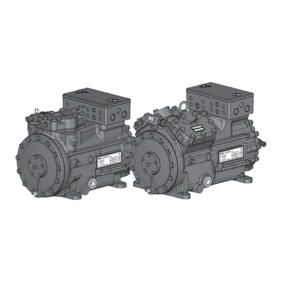
Oil sight glass Fig. 1 HG22e Terminal box Cylinder cover Drive section Suction Motor section shut-off valve Fig. 2 HG34e Dimension and connection values can be found in Chapter 9 6 | AQ451923867809en-000301 © Danfoss | Climate Solutions | 2024.07... -
Page 7: Type Key
Motor variant Number of poles Swept volume e-series Numbers of cylinders Size Oil charge ² Series ¹ HG - Hermetic Gas-cooled (suction gas-cooled) ¹ X - Ester oil charge (HFC refrigerant, e.g. R134a, R404A/R507, R407C) ² S - More powerful motor AQ451923867809en-000301 | 7 © Danfoss | Climate Solutions | 2024.07... -
Page 8: Areas Of Application
For operation with frequency converter: - The maximum current and power consumption must not be exceeded. In the case of operation above the mains frequency, the application limit can therefore be limited. (For more on the subject of frequency converters, see chapter 5.8, p. 18) 8 | AQ451923867809en-000301 © Danfoss | Climate Solutions | 2024.07... - Page 9 Prevent the ingress of air at all costs! Max. permissible operating LP = low pressure HP = high pressure pressure (LP/HP) : 19/28 bar AQ451923867809en-000301 | 9 © Danfoss | Climate Solutions | 2024.07...
-
Page 10: Compressor Assembly
Superheating can damage the valve. Remove the pipe supports therefore from the valve for soldering and accordingly cool the valve body during and after soldering. Only solder using inert gas to inhibit oxidation products (scale). 10 | AQ451923867809en-000301 © Danfoss | Climate Solutions | 2024.07... -
Page 11: Pipes
A rule of thumb: Always lay the first pipe section starting from the shut-off valve downwards and parallel to the drive shaft. Rigid As short as fixed point possible Fig. 6 AQ451923867809en-000301 | 11 © Danfoss | Climate Solutions | 2024.07... -
Page 12: Operating The Shut-Off Valves
For systems with long pipes and higher degree of contamination, a filter on the suction-side is recommended. The filter has to be be renewed depending on the degree of contamination (reduced pressure loss). Moisture in the refrigeration circuit can lead to crystal and hydrate formation. For this reason, we recommend using a filter drier and a sight glass with a moisture indicator. 12 | AQ451923867809en-000301 © Danfoss | Climate Solutions | 2024.07... -
Page 13: Information For Contactor And Motor Contactor Selection
400 V Y Direct start Star-delta start Direct start only L1 L2 L1 L2 L1 L2 L1 L2 INFO The connection examples shown refer to the standard version. In the case of special voltages, the instructions affixed to the terminal box apply. AQ451923867809en-000301 | 13 © Danfoss | Climate Solutions | 2024.07... - Page 14 Anschlußkasten Verdichter Compressor terminal box Fig. 11 Cold conductor (PTC sensor) motor winding Thermal protection thermostat (PTC sensor) Load circuit safety switches Control power circuit fuse High pressure safety monitor Safety chain (high/low pressure monitoring ) Release switch (thermostat) 14 | AQ451923867809en-000301 © Danfoss | Climate Solutions | 2024.07...
- Page 15 L1.1 L2.1 L3.1 L1.2 P> Θ Θ Main switch Control voltage switch Compressor motor Compressor contactor INT69 G Electronic trigger unit INT69 G Oil sump heater AQ451923867809en-000301 | 15 © Danfoss | Climate Solutions | 2024.07...
-
Page 16: Electronic Trigger Unit Int69 G
This would destroy the trigger unit INT69 G and PTC sensors. N 43 43 11 X2 1 Θ Θ Θ Steuerstrom- Steuerstrom- Control circuit kreis kreis Θ Fig. 12 Terminal box 16 | AQ451923867809en-000301 © Danfoss | Climate Solutions | 2024.07... -
Page 17: Oil Sump Heater
Connection: The oil sump heater must be connected via an auxiliary contact (or parallel wired auxil- iary contact) of the compressor contactor to a separate electric circuit. El. data: 110 - 240 V AC, 50 - 120 W Fig. 14 ATTENTION Connection to the current path of the safety control chain is not permitted. AQ451923867809en-000301 | 17 © Danfoss | Climate Solutions | 2024.07... -
Page 18: Selection And Operation Of Compressors With Frequency Converters
5. Carry out all designs and installations in accordance with the local safety regulations and common rules (e.g. VDE) and regulations as well as in accordance with the specifications of the frequency converter manufacturer The permissible frequency range can be found in the technical data. Rotational speed 0 - f-min f-min - f-max range Start-up time < 1 s ca. 4 s immediately Switch-off time f-min/f-max see chapter: Technical data: adjustable frequency range 18 | AQ451923867809en-000301 © Danfoss | Climate Solutions | 2024.07... -
Page 19: Commissioning
Evacuate the suction and discharge pressure sides using the vacuum pump. At the end of the evacuation process, the vacuum should be < 1.5 mbar when the pump is switched off. Repeat this process as often as is required. AQ451923867809en-000301 | 19 © Danfoss | Climate Solutions | 2024.07... -
Page 20: Refrigerant Charge
Only then may the speed of the compressor be reduced. Check the oil level by: The oil must be visible in the sightglass. ATTENTION I f larger quantities of oil have to be topped up, there is a risk of oil hammer effects. If this is the case check the oil return! 20 | AQ451923867809en-000301 © Danfoss | Climate Solutions | 2024.07... -
Page 21: Avoiding Slugging
Otherwise there is a risk of back condensation, which can result in compressor damage. 6.8 Connection of oil level regulator The connection "O" is provided for installing an oil level regulator. A corresponding adapter must be obtained from the trade. AQ451923867809en-000301 | 21 © Danfoss | Climate Solutions | 2024.07... -
Page 22: Maintenance
7.4 Spare parts recommendation/accessories Available spare parts and accessories can be found on our compressor selection tool under vap.bock.de as well as at bockshop.bock.de. Only use genuine Bock spare parts! 22 | AQ451923867809en-000301 © Danfoss | Climate Solutions | 2024.07... -
Page 23: Lubricants / Oil
Close the shut-off valves on the compressor. Drain the refrigerant (it must not be discharged into the environment) and dispose of it according to the regulations. When the compressor is depressurised, undo the fastening screws of the shut-off valves. Remove the compressor using an appropriate hoist. Dispose of the oil inside in accordance with the applicable national regulations. AQ451923867809en-000301 | 23 © Danfoss | Climate Solutions | 2024.07... -
Page 24: Technical Data
220-240 V ∆ / 380-420 V Y - 3 - 50 Hz Voltage 265-290 V ∆ / 440-480 V Y - 3 - 60 Hz Displacement (1450 / 1740 rpm) No. of cylinders Type HG22e/ 24 | AQ451923867809en-000301 © Danfoss | Climate Solutions | 2024.07... - Page 25 220-240 V ∆ / 380-420 V Y - 3 - 50 Hz Voltage 265-290 V ∆ / 440-480 V Y - 3 - 60 Hz Displacement (1450 / 1740 rpm) No. of cylinders Type HG34e/ AQ451923867809en-000301 | 25 © Danfoss | Climate Solutions | 2024.07...
-
Page 26: Dimensions And Connections
1 1 / 8 “- 18 UNEF Sight glass Connection thermal protection thermostat 8 “ NPTF Oil filter M12 x 1,5 1 1 / 8 “- 18 UNEF Connection oil level regulator 26 | AQ451923867809en-000301 © Danfoss | Climate Solutions | 2024.07... - Page 27 Sight glass Connection thermal protection thermostat 8 “ NPTF Oil filter M12 x 1,5 1 1 / 8 “- 18 UNEF Connection oil level regulator Connection for refrigerant injection 8 “ NPTF AQ451923867809en-000301 | 27 © Danfoss | Climate Solutions | 2024.07...
-
Page 28: Declaration Of Incorporation
#3A1, Bommasandra Industrial Area, Hebbagodi, Bock GmbH Hosur Road, Bangalore – 560099 Alexander Layh Benzstraße 7 72636 Frickenhausen, Germany Sivakumar Gopalan, Head - Operations, BOCK India - CC-HP Frickenhausen, 05th of December 2023 28 | AQ451923867809en-000301 © Danfoss | Climate Solutions | 2024.07... - Page 29 #3A1, Bommasandra Industrial Area, Hebbagodi, Danfoss LTD., 22 Wycombe End, Hosur Road, Bangalore – 560099 HP9 1NB, GB Sivakumar Gopalan, Head - Operations, BOCK India - CC-HP Frickenhausen, 05th of December 2023 AQ451923867809en-000301 | 29 © Danfoss | Climate Solutions | 2024.07...
- Page 30 © Danfoss | Climate Solutions | 2024.07 30 | AQ451923867809en-000301...
Need help?
Do you have a question about the BOCK HG22e and is the answer not in the manual?
Questions and answers