Table of Contents
Advertisement
Quick Links
HG 4
®
BOCK
Operating guide
HG4/310-4
HG4/385-4
HG4/465-4
HG4/555-4
HG4/650-4
Translation of the original instructions
HG4/310-4 S
HG4/385-4 S
HG4/465-4 S
HG4/555-4 S
HG4/650-4 S
y
an
st r.
7
m
G er
nz
n,
, Be
se
bH
au
G m
nh
ic ke
ck
6 Fr
Bo
72
63
HGX4/310-4
HGX4/385-4
HGX4/465-4
HGX4/555-4
HGX4/650-4
HGX4/310-4 S
HGX4/385-4 S
HGX4/465-4 S
HGX4/555-4 S
HGX4/650-4 S
AQ452034894212en-000201
Advertisement
Table of Contents

Related Manuals for Danfoss BOCK HG4


Summary of Contents for Danfoss BOCK HG4
- Page 1 st r. G er , Be ic ke 6 Fr HG 4 ® BOCK Operating guide HG4/310-4 HG4/310-4 S HGX4/310-4 HGX4/310-4 S HG4/385-4 HG4/385-4 S HGX4/385-4 HGX4/385-4 S HG4/465-4 HG4/465-4 S HGX4/465-4 HGX4/465-4 S HG4/555-4 HG4/555-4 S HGX4/555-4 HGX4/555-4 S HG4/650-4 HG4/650-4 S HGX4/650-4 HGX4/650-4 S Translation of the original instructions AQ452034894212en-000201...
- Page 2 Observe the safety instructions contained in these instructions. These instructions must be passed onto the end customer along with the unit in which the compres- sor is installed. 2 | AQ452034894212en-000201 © Danfoss | Climate Solutions | 2023.06...
-
Page 3: Table Of Contents
6.8 Connection of oil level regulator Maintenance 7.1 Preparation 7.2 Work to be carried out 7.3 Spare parts recommendation/accessories 7.4 Lubricants / oil 7.5 Decommissioning Technical data Dimensions and connections Declaration of incorporation AQ452034894212en-000201 | 3 © Danfoss | Climate Solutions | 2023.06... -
Page 4: Safety
60 °C on the pressure side or below 0 °C on the suction side can be reached. • The maximum permissible overpressure must not be exceeded, even for testing purposes. 4 | AQ452034894212en-000201 © Danfoss | Climate Solutions | 2023.06... -
Page 5: Intended Use
Commissioning is only permissible if the compressor has been installed in accordance with these assembly instructions and the entire system into which it is integrated has been inspected and approved in accordance with legal regulations. AQ452034894212en-000201 | 5 © Danfoss | Climate Solutions | 2023.06... -
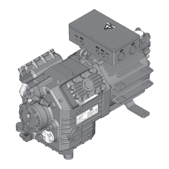
Page 6: Product Description
Name plate Oil pump st r. G er , Be ic ke 6 Fr Drive section Oil sight glass Fig. 1 Dimension and connection values can be found in Chapter 9 6 | AQ452034894212en-000201 © Danfoss | Climate Solutions | 2023.06... -
Page 7: Type Key
Series ¹ ¹ HG - Hermetic Gas-cooled (suction gas-cooled) ² X - Ester oil charge (HFC refrigerant, e.g. R134a, R404A/R507, R407C) S - More powerful motor, e.g. for air-conditioning applications AQ452034894212en-000201 | 7 © Danfoss | Climate Solutions | 2023.06... -
Page 8: Areas Of Application
W hen operating in the vacuum range, there is a danger of air e ntering on the suction side. This can cause chemical reactions, a pressure rise in the condenser and an elevated compressed-gas temperature. Prevent the ingress of air at all costs! 8 | AQ452034894212en-000201 © Danfoss | Climate Solutions | 2023.06... - Page 9 Condensing temperature (°C) Suction gas superheat (K) Suction gas temperature (°C) Max. permissible operating pressure (LP/HP) : 19/28 bar LP = Low pressure HP = High pressure Design for other areas on request Fig. 7 AQ452034894212en-000201 | 9 © Danfoss | Climate Solutions | 2023.06...
-
Page 10: Compressor Assembly
Single compressor preferably on vibration damper. Duplex and parallel circuits always rigid. Fig. 12 4.3 Pipe connections ATTENTION! Superheating can damage the valve. Remove the pipe supports from the valve for soldering. Only solder using inert gas to inhibit oxidation products (scale). 10 | AQ452034894212en-000201 © Danfoss | Climate Solutions | 2023.06... -
Page 11: Pipes
7 , Ger r. 7 , Ben , Ger k Gm , Ben Fric k Gm Fric Rigid fixed point As short as possible Fig. 14 AQ452034894212en-000201 | 11 © Danfoss | Climate Solutions | 2023.06... -
Page 12: Operating The Shut-Off Valves
—> Service connection opened / shut-off valve opened. The connection which cannot be shut off is intended for safety devices. After activating the spindle, generally fit the spindle protection cap again and tighten with 14-16 Nm. This serves as a second sealing feature during operation. 12 | AQ452034894212en-000201 © Danfoss | Climate Solutions | 2023.06... -
Page 13: Electrical Connection 13 Gb
65% of that for a direct start. INFO! A mechanical unloaded start with bypass solenoid valve is not required. AQ452034894212en-000201 | 13 © Danfoss | Climate Solutions | 2023.06... -
Page 14: Basic Circuit Diagram For Part Winding Start With Standard Motor
Control power circuit fuse High pressure safety monitor Safety chain (high/low pressure monitoring) Oil differential pressure monitor Release switch (thermostat) Datum 20.Feb.2009 Bearb. Kelich Gepr. 09.M„r.2010 Žnderung Datum Name Norm Urspr. Ers.f. Ers.d. 14 | AQ452034894212en-000201 © Danfoss | Climate Solutions | 2023.06... - Page 15 L1.2 P> P< P™l Main switch Compressor motor Mains contactor (part winding 1) Mains contactor (part winding 2) Delay relay max. 1s Control voltage switch Oil sump heater PWMP10 BOCKCOMPRESSORS AQ452034894212en-000201 | 15 © Danfoss | Climate Solutions | 2023.06...
- Page 16 ATTENTION! F ailure to do this results in opposed rotary fields and results in damage to the motor. After the motor starts up via partial winding 1, partial winding 2 must be switched on after a maximum delay of one second . Failure to comply can adversely affect the service life of the motor. 16 | AQ452034894212en-000201 © Danfoss | Climate Solutions | 2023.06...
- Page 17 Designation on the name plate Sticker on the terminal box ∆ ∆ ∆ ∆ / Y ∆ ∆ ∆ Star-delta start-up is only possible for 230 V power supply. Example: ∆ 230 V ∆ ∆ 400 V Y ∆ Direct start Star-delta start Direct start only AQ452034894212en-000201 | 17 © Danfoss | Climate Solutions | 2023.06...
- Page 18 High pressure safety monitor Safety chain (high/low pressure monitoring) Oil differential pressure monitor Enabling switch (thermostat) Datum 20.Feb.2009 Main switch Bearb. Kelich Gepr. 09.M„r.2010 Žnderung Datum Name Norm Urspr. Ers.f. Ers.d. 18 | AQ452034894212en-000201 © Danfoss | Climate Solutions | 2023.06...
- Page 19 P> P< P™l Compressor motor Mains contactor ∆ -contactor Y-contactor Delay relay for contactor changeover Delay relay for start unloader Control voltage switch Start unloader MP10 Oil sump heater BOCKCOMPRESSORS AQ452034894212en-000201 | 19 © Danfoss | Climate Solutions | 2023.06...
- Page 20 This would destroy the trigger unit and PTC sensors. The supply voltage at L1-N Terminal board (+/- for DC 24 V version) must be identical to the voltage at terminals 11, 12, 14 and 43. Fig. 21 20 | AQ452034894212en-000201 © Danfoss | Climate Solutions | 2023.06...
- Page 21 • Reconnect terminals 1 or 2 and/or 3 or 4 Restore the power supply (L1 or S1): • MP 10 is operational again • The compressor and the trigger unit MP10 are operational when the H3 LED (green) lights. AQ452034894212en-000201 | 21 © Danfoss | Climate Solutions | 2023.06...
-
Page 22: Oil Sump Heater (Accessories)
Electrical data: 230 V - 1 - 50/60 Hz, 80 W. Fig. 22 ATTENTION! Connection to the current path of the safety control chain is not permitted 22 | AQ452034894212en-000201 © Danfoss | Climate Solutions | 2023.06... -
Page 23: Commissioning
Evacuate the suction and discharge pressure sides using the vacuum pump. At the end of the evacuation process, the vacuum should be < 1.5 mbar when the pump is switched off. Repeat this process as often as is required. AQ452034894212en-000201 | 23 © Danfoss | Climate Solutions | 2023.06... -
Page 24: Refrigerant Charge
Suction gas superheating at the compressor input should be min. 7 - 10 K (check the setting of the expansion valve). The system must reach a state of equilibrium. P articularly in critical systems (e.g. several evaporator points), measures such as the use of liquid traps, solenoid valve in the liquid line, etc. are recommended. There should be no movement of refrigerant in the compressor while the system is at a standstill. 24 | AQ452034894212en-000201 © Danfoss | Climate Solutions | 2023.06... -
Page 25: Connection Of Oil Level Regulator
Dispose of used oil according to the regulations; observe national regulations. Annual checks: Oil level, leak tightness, running noises, pressures, temperatures, function of auxiliary devices such as oil sump heater, pressure switch. AQ452034894212en-000201 | 25 © Danfoss | Climate Solutions | 2023.06... -
Page 26: Spare Parts Recommendation/Accessories
When the compressor is depressurised, undo the fastening screws of the shut-off valves. Remove the compressor using an appropriate hoist. Dispose of the oil inside in accordance with the applicable national regulations. 26 | AQ452034894212en-000201 © Danfoss | Climate Solutions | 2023.06... -
Page 27: Technical Data
380-420 V Y/YY - 3 - 50 Hz PW 440-480 V Y/YY - 3 - 60 Hz PW PW = Part Winding Winding ratio : 66% / 33% No. of cylinders AQ452034894212en-000201 | 27 © Danfoss | Climate Solutions | 2023.06... -
Page 28: Dimensions And Connections
Connection therm Maße in mm View HG(X)4/310-555 -4 (S) SV 90° rotatable Dimensions in mm Dimensions in ( ) = HG(X)4/310-4 (S), HG(X)4/385-4 (S) HG(X)4/465-4 (S), HG(X)4/555-4 (S) Fig. 24 28 | AQ452034894212en-000201 © Danfoss | Climate Solutions | 2023.06... - Page 29 Connection oil level regulator 3 x M6 ÖV Connection oil service valve 4 “ NPTF Connection oil differential pressure sensor M20 x 1,5 Connection oil temperature sensor 8 “ NPTF AQ452034894212en-000201 | 29 © Danfoss | Climate Solutions | 2023.06...
-
Page 30: Declaration Of Incorporation
Bock GmbH Authorized person for compiling and handing Alexander Layh over technical documentation: Benzstraße 7 72636 Frickenhausen, Germany Frickenhausen, 04th of January 2021 i. A. Alexander Layh, Global Head of R&D 30 | AQ452034894212en-000201 © Danfoss | Climate Solutions | 2023.06... - Page 31 AQ452034894212en-000201 | 31 © Danfoss | Climate Solutions | 2023.06...
- Page 32 32 | AQ452034894212en-000201 © Danfoss | Climate Solutions | 2023.06...
Need help?
Do you have a question about the BOCK HG4 and is the answer not in the manual?
Questions and answers