Table of Contents
Advertisement
Quick Links
HGX 34 CO
®
BOCK
Operating guide
HGX34/110-4 (ML)(S)(SH) CO
HGX34/150-4 (ML)(S)(SH) CO
HGX34/190-4 (ML)(S)(SH) CO
HGX34/230-4 (ML)(S)(SH) CO
HGX34/110 MLP 11 CO
HGX34/130 MLP 14 CO
HGX34/150 MLP 16 CO
HGX34/170 MLP 19 CO
HGX34/190 MLP 22 CO
HGX34/210 MLP 24 CO
HGX34/230 MLP 26 CO
HGX34/290 MLP 34 CO
Translation of the original instructions
HGX34/130-4 (ML)(S)(SH) CO
T
2
HGX34/170-4 (ML)(S)(SH) CO
T
2
HGX34/210-4 (ML)(S)(SH) CO
T
2
HGX34/290-4 (ML)(S)(SH) CO
T
2
HGX34/110 (SP)(SHP) 16 CO
T
2
HGX34/130 (SP)(SHP) 19 CO
T
2
HGX34/150 (SP)(SHP) 22 CO
T
2
HGX34/170 (SP)(SHP) 28 CO
T
2
HGX34/190 (SP)(SHP) 30 CO
T
2
HGX34/210 (SP)(SHP) 31 CO
T
2
HGX34/230 (SP)(SHP) 35 CO
T
2
HGX34/290 (SP)(SHP) 48 CO
T
2
T
2
T
2
T
2
T
2
T
2
T
2
T
2
T
2
T
2
T
2
T
2
T
2
T
2
AQ452523677525en-000201
Advertisement
Table of Contents

Subscribe to Our Youtube Channel
Related Manuals for Danfoss BOCK HGX34 CO2 T Series


Summary of Contents for Danfoss BOCK HGX34 CO2 T Series
- Page 1 HGX 34 CO ® BOCK Operating guide HGX34/110-4 (ML)(S)(SH) CO HGX34/130-4 (ML)(S)(SH) CO HGX34/150-4 (ML)(S)(SH) CO HGX34/170-4 (ML)(S)(SH) CO HGX34/190-4 (ML)(S)(SH) CO HGX34/210-4 (ML)(S)(SH) CO HGX34/230-4 (ML)(S)(SH) CO HGX34/290-4 (ML)(S)(SH) CO HGX34/110 MLP 11 CO HGX34/110 (SP)(SHP) 16 CO HGX34/130 MLP 14 CO HGX34/130 (SP)(SHP) 19 CO HGX34/150 MLP 16 CO HGX34/150 (SP)(SHP) 22 CO...
-
Page 2: Table Of Contents
4.9 Operating mode of the lockable service connections 4.10 Oil return 4.11 Suction pipe filter Electrical connection 5.1 Information for contactor and motor contactor selection 5.2 Standard motor, designed for direct or part winding start 2 | AQ452523677525en-000201 © Danfoss | Climate Solutions | 2023.07... - Page 3 6.10 Filter dryer Maintenance 7.1 Preparation 7.2 Work to be carried out 7.3 Spare parts recommendation / accessories 7.4 Lubricants / oil 7.5 Decommissioning Technical data Dimensions and connections Declaration of incorporation AQ452523677525en-000201 | 3 © Danfoss | Climate Solutions | 2023.07...
-
Page 4: Safety
As well as professions with comparable training, which enable personnel to assemble, install, maintain and repair refrigeration and air-conditioning systems. Personnel must be capable of assessing the work to be carried out and recognising any potential dangers. 4 | AQ452523677525en-000201 © Danfoss | Climate Solutions | 2023.07... -
Page 5: Safety Instructions
Only the refrigerant specified in these instructions may be used. Any other use of the compressor is prohibited! AQ452523677525en-000201 | 5 © Danfoss | Climate Solutions | 2023.07... -
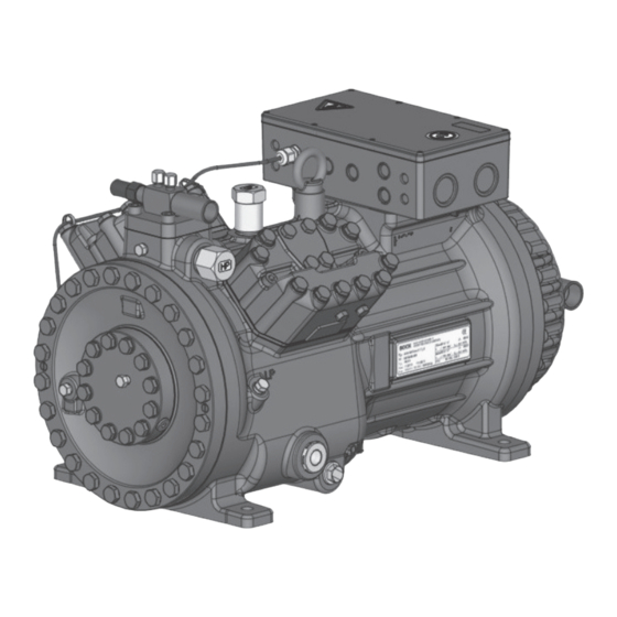
Page 6: D 2 Product Description
Name plate Oil pump Oil sight glass Fig. 1 Discharge shut-off valve Terminal box Cylinder cover Suction shut-off valve Fig. 2 Dimension and connection values can be found in chapter 9 6 | AQ452523677525en-000201 © Danfoss | Climate Solutions | 2023.07... -
Page 7: Type Key
ML - Normal cooling and deep freezing at low and medium evaporation temperatures ³ - For frequency regulation and extended limits of application SH - For high evaporating temperatures eg. heat pumps, different oil charge AQ452523677525en-000201 | 7 © Danfoss | Climate Solutions | 2023.07... -
Page 8: Type Key Compressors With Lspm Motor (Line Start Permanent Magnet)
The oil level must be in the visible part of the sight glass; Max. damage to the compressor Oil level 0.9 Ltr. is possible if overfilled or Min. underfilled! Fig. 4 8 | AQ452523677525en-000201 © Danfoss | Climate Solutions | 2023.07... -
Page 9: Limits Of Application
10 % - 95 %, no condensation. Do not store in a corrosive, dusty, vaporous atmosphere or in a com- bustible environment. Use transport eyelet. Do not lift manually! Use lifting gear! AQ452523677525en-000201 | 9 © Danfoss | Climate Solutions | 2023.07... -
Page 10: Setting Up
On its high-pressure side, the compressor has a shut-off valve with multi-sided cutting ring for safe • installation of the discharge line. Cutting ring function after tightening the union nut Collar Fig. 6 Figure similar 10 | AQ452523677525en-000201 © Danfoss | Climate Solutions | 2023.07... -
Page 11: Pipes
Risk of injury. CAUTION The compressor must be depressurized through connections A and B before commencing any work and prior to connecting to the refrig- erant system. Fig. 7 Fig. 8 AQ452523677525en-000201 | 11 © Danfoss | Climate Solutions | 2023.07... -
Page 12: Laying Suction And Pressure Lines
Before opening or closing the shut-off valve, release the valve spindle seal by approx. of a turn counter-clockwise. After activating the shut-off valve, re-tighten the adjustable valve spindle seal clockwise. Tighten Release Valve spindle seal Fig. 10 Fig. 11 12 | AQ452523677525en-000201 © Danfoss | Climate Solutions | 2023.07... -
Page 13: Operating Mode Of The Lockable Service Connections
For systems with long pipes and higher degree of contamination, a filter on the suction-side is recommended. The filter has to be be renewed depending on the degree of contamina- tion (reduced pressure loss). AQ452523677525en-000201 | 13 © Danfoss | Climate Solutions | 2023.07... -
Page 14: Electrical Connection
Adjust the overload protection device so that it must be actuated within 2 hours at 1.2 times the maximum working current. For compressors with LSPM motor, a faster responding overload protection device is recommended. 14 | AQ452523677525en-000201 © Danfoss | Climate Solutions | 2023.07... -
Page 15: Standard Motor, Designed For Direct Or Part Winding Start
(1U1 / 1V1 / 1W1) and via QA3 to winding 2 (50 %) (2U1 / 2V1 / 2W1). The motor contactors (QA2 / QA3) are each to be rated for approx. 50 % of the max. operating current. AQ452523677525en-000201 | 15 © Danfoss | Climate Solutions | 2023.07... -
Page 16: Basic Circuit Diagram For Part Winding Start
DELTA-P II Oil differential pressure sensor DELTA-P II (accessory) Bearb. bauknecht Oil sump heater Gepr. 26.11.2020 Compressor motor Οnderung Datum Name Norm Urspr. Ers. f. Ers. d. * With several connect them in series 16 | AQ452523677525en-000201 © Danfoss | Climate Solutions | 2023.07... - Page 17 Electronic trigger unit INT69 G Delay relay for contactor switch over Main switch PW INT69 HG44/66 Mains contactor (part winding 1) Mains contactor (part winding 2) BOCK COMPRESSORS Control voltage switch AQ452523677525en-000201 | 17 © Danfoss | Climate Solutions | 2023.07...
-
Page 18: Special Motor: Design For Direct Or Star-Delta Start
5 | Electrical connection 5.4 Special motor: design for direct or star-delta start Designation on the name plate ∆ / Y 18 | AQ452523677525en-000201 © Danfoss | Climate Solutions | 2023.07... - Page 19 Star-delta start-up is only possible for 230 V power supply. Example: 230 V Δ 400 V Y Direct start Star-delta start Direct start only (not on LSPM Motor) Only direct start is possible with LSPM Motor. AQ452523677525en-000201 | 19 © Danfoss | Climate Solutions | 2023.07...
-
Page 20: Basic Circuit Diagram For Star-Delta Start With Special Motor
DELTA PII Oil differential pressure sensor DELTA-P II (accessory) Bearb. bauknecht Oil sump heater Gepr. 03.11.2020 Compressor motor Οnderung Datum Name Norm Urspr. Ers. f. Ers. d. * With several connect them in series 20 | AQ452523677525en-000201 © Danfoss | Climate Solutions | 2023.07... - Page 21 Control power circuit fuse INT69 G Electronic trigger unit INT69 G Delay relay for contactor switch over Main switch Mains contactor D/S INT69 HG44/66 neu Δ-contactor BOCK COMPRESSORS Y-contactor Control voltage switch AQ452523677525en-000201 | 21 © Danfoss | Climate Solutions | 2023.07...
-
Page 22: Electronic Trigger Unit Int69 G
5.8 Function test of the trigger unit INT69 G Before commissioning, after troubleshooting or making changes to the control power circuit, check the functionality of the trigger unit. Perform this check using a continuity tester or gauge. 22 | AQ452523677525en-000201 © Danfoss | Climate Solutions | 2023.07... -
Page 23: Oil Sump Heater
For start-up and low speed operation, a voltage boost of 10-20V is recommended to slightly reduce the motor current and compensate for voltage drops through the compressor supply line (and filtering devices, if present). AQ452523677525en-000201 | 23 © Danfoss | Climate Solutions | 2023.07... -
Page 24: Commissioning
Only dry test gases may be used for the leak test, e.g. nitrogen N2 min. 4.6 (= purity 99.996 % or higher). 24 | AQ452523677525en-000201 © Danfoss | Climate Solutions | 2023.07... -
Page 25: Evacuation
Avoid overfilling the machine with refrigerant! ATTENTION Do not charge liquid refrigerant into the suction-side on the compressor. Do not mix additives with the oil and refrigerant. AQ452523677525en-000201 | 25 © Danfoss | Climate Solutions | 2023.07... -
Page 26: Start-Up
(con- nections A and B, see Chapter 9). 26 | AQ452523677525en-000201 © Danfoss | Climate Solutions | 2023.07... -
Page 27: Decompression Valves
EN 378-2 or appropriate safety standards. Failure to observe can result in risk of injury from CO streaming out of the two decompression valves! streaming Fig. 18 AQ452523677525en-000201 | 27 © Danfoss | Climate Solutions | 2023.07... -
Page 28: Avoiding Slugging
CO is produced which blocks the outlet and . Otherwise, there is the could hinder the streaming out of CO danger that pressure can be built up again. 28 | AQ452523677525en-000201 © Danfoss | Climate Solutions | 2023.07... -
Page 29: Work To Be Carried Out Gb
For this reason the suction side (LP) and the high pressure side (HP) of the compressor have to be secured by decompression valves. AQ452523677525en-000201 | 29 © Danfoss | Climate Solutions | 2023.07... -
Page 30: Technical Data
440-480 V Y/YY - 3 - 60 Hz PW Voltage PW = Part Winding Winding ratio : 50 % / 50 % Displacement (1450 / 1740 rpm) No. of cylinders Type HGX34/ 30 | AQ452523677525en-000201 © Danfoss | Climate Solutions | 2023.07... - Page 31 380-420 V Y/YY - 3 - 50 Hz PW 440-480 V Y/YY - 3 - 60 Hz PW PW = Part Winding Winding ratio : 50 % / 50 % AQ452523677525en-000201 | 31 © Danfoss | Climate Solutions | 2023.07...
- Page 32 220-240 V ∆ / 380-420 V Y - 3 - 50 Hz Voltage 265-290 V ∆ / 440-480 V Y - 3 - 60 Hz Displacement (1500 / 1800 rpm) No. of cylinders Type HGX34/ 32 | AQ452523677525en-000201 © Danfoss | Climate Solutions | 2023.07...
- Page 33 8 | Technical data 20 - 70 220-240 V ∆ / 380-420 V Y - 3 - 50 Hz 265-290 V ∆ / 440-480 V Y - 3 - 60 Hz AQ452523677525en-000201 | 33 © Danfoss | Climate Solutions | 2023.07...
-
Page 34: Dimensions And Connections
0h | Zubehör DCR22 & Heißgastemperatursensor aufgenommen 09.05.22 S. Büttner packaging for safe transportation). 34 | AQ452523677525en-000201 © Danfoss | Climate Solutions | 2023.07 Weitergabe sowie Vervielfältigung dieses Dokuments, 0h | BS-Befestigungsteile aus Lieferumfang entfernt und als Zubehör ergänzt 11614 A. Layh 06.05.22... - Page 35 Decompression valve HP M24x1,5 Decompression valve LP M22x1,5 Connection for Schrader valve, suction side 7 / 16 “ UNF 7 / 16 “ UNF Connection for Schrader valve, discharge side AQ452523677525en-000201 | 35 © Danfoss | Climate Solutions | 2023.07...
-
Page 36: Declaration Of Incorporation
Bock GmbH Authorized person for compiling and handing Alexander Layh over technical documentation: Benzstraße 7 72636 Frickenhausen, Germany Frickenhausen, 04th of January 2021 i. A. Alexander Layh, Global Head of R&D 36 | AQ452523677525en-000201 © Danfoss | Climate Solutions | 2023.07... - Page 37 Bock GmbH Authorized person for compiling and handing Alexander Layh over technical documentation: Benzstraße 7 72636 Frickenhausen, Germany Frickenhausen, 14th of October 2022 i. A. Alexander Layh, Global Head of R&D AQ452523677525en-000201 | 37 © Danfoss | Climate Solutions | 2023.07...
- Page 38 38 | AQ452523677525en-000201 © Danfoss | Climate Solutions | 2023.07...
Need help?
Do you have a question about the BOCK HGX34 CO2 T Series and is the answer not in the manual?
Questions and answers