
Subscribe to Our Youtube Channel
Related Manuals for Wampat W06F3030W


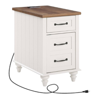
Summary of Contents for Wampat W06F3030W
- Page 1 Assembly Instructions W06F3030W Please read this manual carefully before beginning assembly of this product.Keep this manual for future reference.
- Page 4 Wooden dowel Wooden dowel Cam lock Cam bolt Cam lock Glue tube Ø8x30mm Ø8x20mm Ø15x11mm Ø7x34mm Ø14x11mm x 16 x 16 x 16 Screw Footpads Screw Handle Cam bolt HANDLE BOLT 4x12x8mm Ø4x25 Ø4x30 Ø6x29mm Screw Plastic wedge Flat-head screw Magnetic catch Metal piece WOOD SCREW...
- Page 5 ● The provided glue(A) is to secure wood dowels(B) in place . When first inserting dowels, locate the appropriate hole for the dowel , place a small amount of glue in the hole and insert the dowel . Wipe away excess glue immediately.
- Page 6 · Attach panels (5) to panels (3,4). · Insert and secure cam locks (D) to panels (3,4) to lock it.
- Page 7 · Attach panels (6) to panels (3,4) with screws (K) correctly.
- Page 8 · Separate the slider bracket from the slider arm as per diagram.
- Page 9 1.375" 5.15" 10.2" · Attach slider arms to panels (3,4) with screws (S) correctly.
- Page 10 · Insert dowels (B) into panels (7,16). · Attach part (P) to panel (7) with screws (Q) correctly.
- Page 11 · Attach panels (3,4) to panels (7,16). · Insert and secure cam locks (D) to panels (7,16) to lock it.
- Page 12 · Attach panel (2) to panels (3,4) with screws (M) correctly.
- Page 13 · Install the legs (8) to panel (2). · Stick the Footpads (J) to legs (8).
- Page 14 · Stick stickers (X) on legs (8). · Slide panel (15) into designated area correctly.
- Page 15 · Screw cam bolts (E) into panel (1).
- Page 16 · Insert and secure cam locks (D) to panels (3,4) to lock it.
- Page 17 · Secure parts (N) to panel (15) with screws (O).
- Page 18 · Attach hinge-top (W) to panel (9) with screws (S) correctly. · Attach part (R) to panel (9) with screw (S) correctly.
- Page 19 · Attach handles (H) to panel (9) with bolts (I) correctly.
- Page 20 · Insert door shaft support (U) into panels (2,7).
- Page 21 · Insert Hinge-bottom (V) to panel (2). · Insert panel (9) to panel (2). · Attach Hinge-bottom (V) to panel (9) with screws (S).
- Page 22 · Attach panels (11,12) to panel (13) with screws (L) correctly. · Carefully slide panels (14) into place along the bottom of the assembly.
- Page 23 · Screw cam bolts (G) into panel (10). · Attach handle (H) to panel (10) with bolts (I) correctly.
- Page 24 · Attach panel (10) to panels (11,12). · Insert and secure cam locks (F) to panels (11,12) to lock it.
- Page 25 · Attach slider brackets to panels (11,12) with screws (S) correctly.
- Page 26 Slider arm Slider bracket Slider bracket · Assembled the drawers as per diagram Note :If the drawer does not go in smoothly. Press or lift the plastic release lever. Pull out the slider bracket from the slider arm then re-assembled the drawer until they were going in smoothly well.
- Page 27 · Attach socket (Y) to panel (1) with screws (S) correctly.
- Page 28 · Stick stickers (X) on cam locks (D). x 16 . To adjust side ways. Loosen screws (S) and adjust door, then tighten screws (S). . To adjust depth. Loosen screws (Q) and adjust Magnetic catch (P), then tighten screws (Q).
Need help?
Do you have a question about the W06F3030W and is the answer not in the manual?
Questions and answers