Advertisement
Advertisement
Table of Contents

Subscribe to Our Youtube Channel
Related Manuals for EK-Quantum Momentum2 Quad RAM Module Set


Summary of Contents for EK-Quantum Momentum2 Quad RAM Module Set
- Page 1 EK-Quantum Momentum Quad RAM Module Set USER GUIDE...
- Page 2 This product is intended for installation only by expert users. Please consult with a qualified technician for installation. Improper installation may result in damage to your equipment. EK Water Blocks assumes no liability whatsoever, expressed or implied, for the use of these products, or their installation. The following instructions are subject to change without notice.
-
Page 3: Table Of Contents
RAM WB TECHNICAL SPECIFICATIONS AND PRODUCT PARTS Memory module Ek-Quantum Momentum RAM WB PREPARING AND INSTALLING THE MEMORY MODULE PREPARING AND INSTALLING THE EK-Quantum Momentum RAM WB FITTINGS AND TUBING CONNECTING THE D-RGB LED STRIP TESTING THE LOOP SUPPORT AND SERVICE... -
Page 4: Ek-Quantum Momentum
BOX CONTENTS Memory module (4 pcs) EK-Quantum Momentum RAM WB (1 pc) Thermal Pad G 1.0 mm (8 pcs) Thermal Pad F 1.0 mm (2 pcs) Screw M3 x 8 DIN7984 (8 pcs) Allen Key 2 mm (1 pc) EAN: 3830046996770... -
Page 5: Memory Module
PRODUCT DIMENSIONS Memory module 139 mm 8.3 mm 126.5 mm 4.3 mm EK-Quantum Momentum RAM WB 139 mm 108 mm 31 mm 77 mm - 5 -... - Page 6 TECHNICAL SPECIFICATIONS AND PRODUCT PARTS Memory module Position Description Quantity 107638 Top Cover (Black e.) 107641 Side cover (Black e.) 8211 Screw M3x5 DIN7991 100663 EK - Badge - 6 -...
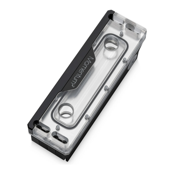
- Page 7 Ek-Quantum Momentum RAM WB Position Description Quantity 107273 Coldplate (Ni) 107275 Top plate (Plexi) 107274 Top plate (Acetal) 103952 Mylar sticker 103154 LED D-RGB Strip 8104A Screw M2.5 x 8 mm AX1 8201 Screw M3 x 10 7991DIN 5103 OR 73 x 1.5 mm...
-
Page 8: Preparing And Installing The Memory Module
PREPARING AND INSTALLING THE MEMORY MODULE STEP 1 In case your Memory modules are equipped with heat spreaders by default it is mandatory to remove those before continuing the installation process. Because there is no prescribed standard on how the heat spreader should be attached to the memory module, many methods are used, the most common being self-adhesive tape between the heat spreader and memory IC. - Page 9 STEP 4 Insert the Memory module and secure it with previously removed M3 x 5 DIN7991 side cover and screws. Do not use excessive force while securing the module. Repeat this process with the rest of the Memory modules. SIDE COVER For this step, you will need: Side cover M3 x 5 DIN7991 Screws...
-
Page 10: Preparing And Installing The Ek-Quantum Momentum
PREPARING AND INSTALLING THE EK-Quantum Momentum RAM WB STEP 1 THERMAL PAD F 1.0 mm After securing Memory modules, position two (2) provided Thermal Pad F 1.0 mm on the shown places. Remove the protective foil from both sides of the thermal pad before installation. - Page 11 STEP 3 M3 x 8 DIN7984 Secure the water block with the provided mounting screws M3 x 8 SCREW DIN7984. For each memory module, two (2) screws must be used. Tighten the screws evenly using the Allen Key 2 mm. For this step, you will need: M3 x 8 DIN7984 Screw Allen Key2mm...
- Page 12 CONNECTING THE D-RGB LED STRIP STEP 1 Plug the 3-pin D-RGB connector from the RAM water block into a D-RGB header on your motherboard or controller. The LED strip will only work if the pin layout on the header is as follows: +5V, Digital, Empty, Ground.
- Page 13 SUPPORT AND SERVICE In case you need assistance or wish to order spare parts or a new mounting mechanism, please contact: https://www.ekwb.com/customer-support/ For spare parts orders, refer to the page with “TECHNICAL SPECIFICATIONS AND PRODUCT PARTS” where you can find the EAN number of each part you might need.
Need help?
Do you have a question about the Momentum2 Quad RAM Module Set and is the answer not in the manual?
Questions and answers