EK-Quantum Momentum2 ROG Crosshair VIII Extreme D-RGB Quick Start Manual
Monoblock
Hide thumbs
Also See for Momentum2 ROG Crosshair VIII Extreme D-RGB:
- User manual (22 pages) ,
- Manual (19 pages) ,
- User manual (18 pages)
Table of Contents
Advertisement
Quick Links
Advertisement
Table of Contents

Related Manuals for EK-Quantum Momentum2 ROG Crosshair VIII Extreme D-RGB


Summary of Contents for EK-Quantum Momentum2 ROG Crosshair VIII Extreme D-RGB
- Page 1 EK-Quantum Momentum ROG Crosshair VIII Extreme D-RGB MONOBLOCK USER GUIDE...
- Page 2 This product is intended for installation only by expert users. Please consult with a qualified technician for installation. Improper installation may result in damage to your equipment. EK Water Blocks assumes no liability whatsoever, expressed or implied, for the use of these products, nor their installation.
-
Page 3: Table Of Contents
TABLE OF CONTENTS BOX CONTENTS WATER BLOCK DIMENSIONS TECHNICAL SPECIFICATIONS AND WATER BLOCK PARTS PREPARING THE MOTHERBOARD CUTTING AND PLACING THERMAL PADS APPLYING THERMAL COMPOUND PREPARING THE WATER BLOCK FOR INSTALLATION ATTACHING THE WATER BLOCK CONNECTING THE D-RGB LED STRIP TESTING THE LOOP SUPPORT AND SERVICE SOCIAL MEDIA... -
Page 4: Box Contents
M2.5x4 AX1 Screw (5 pcs) M2.5 PVC Washer (10 pcs) M2.5x6 AX1 Screw (5 pcs) Allen Key 2.5 mm (1 pc) EK-Quantum Momentum ROG Crosshair VIII Extreme D-RGB Thermal Grease (1 pc) Allen Key 2 mm (1 pc) Thermal Pad G 1.0 mm (120x24) (2 pcs) -
Page 5: Water Block Dimensions
WATER BLOCK DIMENSIONS 127.1 mm 29.2 mm 63 mm - 5 -... -
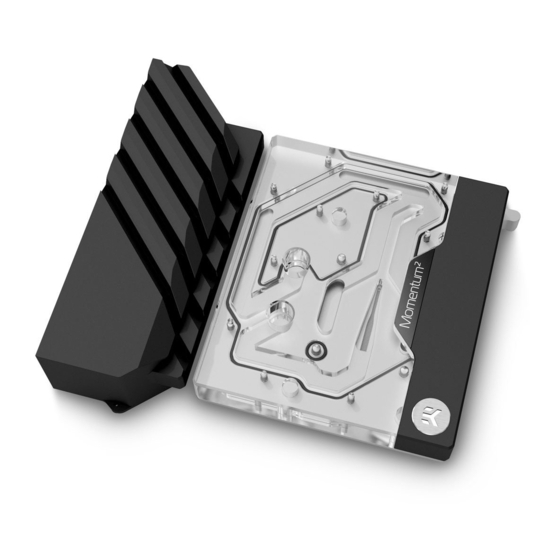
Page 6: Technical Specifications And Water Block Parts
TECHNICAL SPECIFICATIONS AND WATER BLOCK PARTS Technical Specification: - Dimensions: (LxHxW) - 127 x 135 x 32.5mm - D-RGB cable length: 500mm - D-RGB LED count: 8 - D-RGB connector standard 3-pin (+5V, Data, Blocked, Ground) Position Description Quantity 103912 Coldplate (Nickel) 104666 Top plate (Plexi) -
Page 7: Preparing The Motherboard
Place the motherboard on the flat surface and carefully remove the stock cooler and backplate. Do not forget to unplug all the LED connectors. Pay attention to the following steps in order to install the EK-Quantum Momentum² ROG Crosshair VIII Extreme D-RGB water block. -
Page 8: Applying Thermal Compound
APPLYING THERMAL COMPOUND STEP 1 Apply the enclosed EK-TIM Ectotherm thermal grease (thermal compound) on the CPU heat spreader – IHS – as shown in the image. The layer of the thermal compound must be thin and even in thickness over the entire surface of the IHS. The excessive or uneven application of thermal grease may lead to poor performance! For this step, you will need:... -
Page 9: Attaching The Water Block
ATTACHING THE WATER BLOCK STEP 1 Carefully place the water block onto the motherboard and align four (4) mounting screws with four (4) holes on the motherboard. Hold the water block and the motherboard and turn them upside down. Before placing the Water Block on the motherboard, make sure all the Thermal Pads are placed correctly! (Chapter: Cutting and placing thermal pads). - Page 10 STEP 3 After securing the water block, the stored backplate must be attached to the backside of the motherboard using Allen Key 2.5 mm (shown in the picture) or EK-Loop Torque Screwdriver. Start fastening the backplate MAX TORQUE: screws in a cross pattern. Do not tighten fully until all of the nuts are 0.6 Nm ALLEN KEY 2.5 mm partially screwed in.
- Page 11 Phillips Head Screwdriver STEP 5 STEP 6 With the EK-Quantum Momentum² ROG Crosshair VIII Extreme D-RGB, it is mandatory to use the bottom port as the INLET. Mixing the ports may result in poor thermal performance of the water block.
-
Page 12: Connecting The D-Rgb Led Strip
CONNECTING THE D-RGB LED STRIP STEP 1 Plug the 3-Pin connector from the water block’s D-RGB LED light to the DRGB HEADER on the motherboard. The LED will work if the pin layout on the header is as follows: +5V, Digital, empty, Ground. -
Page 13: Support And Service
SUPPORT AND SERVICE In case you need assistance or wish to order spare parts or a new mounting mechanism, please contact: https://www.ekwb.com/customer-support/ For spare parts orders, refer to the page with “TECHNICAL SPECIFICATIONS AND WATER BLOCK PARTS” where you can find the EAN number of each part you might need.
Need help?
Do you have a question about the Momentum2 ROG Crosshair VIII Extreme D-RGB and is the answer not in the manual?
Questions and answers