EK-Quantum Momentum2 ROG Maximus Z790 Extreme D-RGB Special Edition Manual
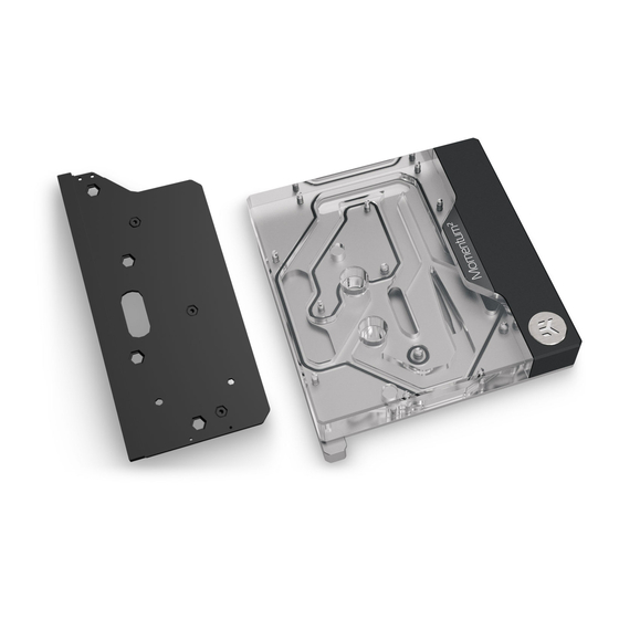
Monoblock
Hide thumbs
Also See for Momentum2 ROG Maximus Z790 Extreme D-RGB Special Edition:
- User manual (22 pages) ,
- Quick start manual (13 pages) ,
- User manual (13 pages)

Related Manuals for EK-Quantum Momentum2 ROG Maximus Z790 Extreme D-RGB Special Edition


Summary of Contents for EK-Quantum Momentum2 ROG Maximus Z790 Extreme D-RGB Special Edition
- Page 1 EK-Quantum Momentum ROG Maximus Z790 Extreme D-RGB - Special Edition MONOBLOCK USER GUIDE...
- Page 2 Please note the installation of the product is intended to be undertaken by an adequately trained and experienced person. You are installing the product at your own risk. If you are not properly trained or experienced or feel unsure about the installation procedure, please refrain from installing the product yourself and contact our tech support for assistance.
-
Page 3: Table Of Contents
TABLE OF CONTENTS BOX CONTENTS WATER BLOCK DIMENSIONS TECHNICAL SPECIFICATIONS AND WATER BLOCK PARTS PREPARING THE MOTHERBOARD REMOVING THE BACKPLATE REMOVING THE STOCK COOLER INSTALLING THE CPU AND DIE GUARD ATTACHING THE REPLACEMENT COVER INSTALLING THE WATER BLOCK CUTTING AND PLACING THERMAL PADS APPLYING THERMAL COMPOUND PLACING THE WATER BLOCK CONNECTING THE 10-PIN SIGNAL SPLITTER... -
Page 4: Box Contents
BOX CONTENTS Replacement cover (1 pc) Die guard + Backplate Assembly (1 pc) EK-Quantum Momentum ROG Maximus Z790 Extreme D-RGB - Special Edition + Mounting mechanism Delidding Tool (1 pc) Replacement I/O cover (1 pc) Thermal Grizzly Conductonaut (1 pc) 10pin Signal Splitter (1 pc) Thermal Pad F 0.5 mm (3 pcs) - Page 5 EK-Quantum Momentum ROG Maximus Z790 Extreme D-RGB - Special Edition - Mounting mechanism EAN: 106546 Allen Key 2 mm (1 pc) Allen Key 2.5 mm (1 pc) Protective sticker (1 pc) Protective Foam 5 mm (1 pc) EK-Plug Out Spludger Tool (1 pc)
-
Page 6: Water Block Dimensions
WATER BLOCK DIMENSIONS 112.5 mm 183 mm 25 mm 78.5 mm - 6 -... -
Page 7: Technical Specifications And Water Block Parts
TECHNICAL SPECIFICATIONS AND WATER BLOCK PARTS Technical Specification: - Dimensions: (L x H x W) – 151.5 x 112.5 x 33 mm - D-RGB cable length: 500 mm - D-RGB LED count: 8 - D-RGB connector standard 3-pin (+5V, Data, Blocked, Ground) Position Description Quantity... -
Page 8: Preparing The Motherboard
PREPARING THE MOTHERBOARD Important! Before starting, make sure to have a clean, flat UNSCREW FROM THE surface to work on. Putting foam or soft material to lay the FRONTSIDE motherboard on is recommended. STEP 1 REMOVING THE BACKPLATE Using a Philips head screwdriver, unscrew six (6) Screws. Rotate the motherboard and remove an additional one (1) screw (Red marked in the picture). -
Page 9: Removing The Stock Cooler
STEP 2 REMOVING THE STOCK COOLER From the front side of the motherboard, unscrew two (2) screws located in the SSD heatsink. Rotate the motherboard and unscrew eight (8) screws from the back of the motherboard. Detach the stock cooler from the motherboard. Save the I/O Screen for later use –... -
Page 10: Installing The Cpu And Die Guard
STEP 3 REMOVING THE CPU SOCKET (MOUNTING MECHANISM) Remove the Tx screws (marked in the picture) and detach the CPU socket mounting mechanism. For this step you will need: Tx20 L-Shaped Wrench (1 pc) STEP 4 INSTALLING THE CPU AND DIE GUARD First, unscrew (4) M3 x 12 DIN7991 Screws from the Die guard + STEP 3 Backplate Assembly. -
Page 11: Attaching The Replacement Cover
ATTACHING THE REPLACEMENT COVER STEP 1 The replacement cover must be attached before installing the Monoblock. Place the F1.5 mm thermal pads (as shown in the picture) onto the replacement cover. EK made sure to provide you with more than an adequate quantity of Thermal Pads to complete this Step. - Page 12 STEP 3 Place the replacement cover onto the motherboard. Make sure to align the mounting holes on the motherboard with the standoffs on the cover. Make sure the LED screen is correctly connected to the motherboard. STEP 3 STEP 4 M2.5 x 5 AX1 SCREW Rotate the motherboard and attach the replacement cover with the M2.5 PVC WASHER...
-
Page 13: Installing The Water Block
INSTALLING THE WATER BLOCK STEP 1 Thermal Pad - 120 x 16 x 0.5 mm CUTTING AND PLACING THERMAL PADS F0.5 Thermal Pad - 120 x 16 x 1.5 mm After attaching the replacement cover, a few additional thermal pads F1.5 must be placed in the places marked in the picture. -
Page 14: Applying Thermal Compound
STEP 2 APPLYING THERMAL COMPOUND Apply the enclosed Thermal Grizzly Hydronaut thermal grease (thermal compound) on the CPU heat spreader – IHS – as shown in the image. The layer of the thermal compound must be thin and even in thickness over the entire surface of the IHS. The excessive or uneven application of thermal grease may lead to poor performance! For this step, you will need:... - Page 15 STEP 4 MAX TORQUE: After placing the water block, fasten the backplate screws in a 0.6 Nm cross pattern. Do not tighten fully until all of the nuts are partially screwed in. ALLEN KEY 2.5 mm Make sure to orientate the backplate as illustrated. TOP OF THE Incorrect installation of the backplate may result in MOTHERBOARD...
-
Page 16: Connecting The 10-Pin Signal Splitter
STEP 5 CONNECTING THE 10-PIN SIGNAL SPLITTER 10-PIN SIGNAL Connect the 10-pin signal splitter connector to the Monoblock. SPLITTER CONNECTOR Please ensure that the arrow indicated on the connector is plugged into the line as indicated on your Monoblock. 10-PIN SIGNAL SPLITTER HEADER The opposite side of the connector must be connected to the motherboard (marked in the picture). -
Page 17: Connecting The D-Rgb Led Strip
STEP 6 CONNECTING THE D-RGB LED STRIP Plug the 3-Pin connector from the water block’s D-RGB LED light to the DRGB HEADER on the motherboard. The LED will work if the pin layout on the header is as follows: +5V, Digital, empty, Ground. D-RGB HEADER Please ensure that the arrow indicated on the connector is plugged into the +5V line as indicated on your motherboard. -
Page 18: Fittings And Tubing
FITTINGS AND TUBING STEP 1 Several tubing configurations are possible for this Monoblock. For more information, check the product page: https://www.ekwb.com/ shop/ek-quantum-momentum2-rog-maximus-z790-extreme-d-rgb- special-edition OUTLET The basic configuration is described below. INLET Option 1: In the shown configuration, it is mandatory to use the bottom port as the INLET. -
Page 19: Support And Service
SUPPORT AND SERVICE In case you need assistance or wish to order spare parts or a new mounting mechanism, please contact: https://www.ekwb.com/customer-support/ For spare parts orders, refer to the page with “TECHNICAL SPECIFICATIONS AND WATER BLOCK PARTS” where you can find the EAN number of each part you might need.
Need help?
Do you have a question about the Momentum2 ROG Maximus Z790 Extreme D-RGB Special Edition and is the answer not in the manual?
Questions and answers