EK-Quantum Momentum2 ROG Maximus Z690 Extreme D-RGB User Manual
Monoblock
Hide thumbs
Also See for Momentum2 ROG Maximus Z690 Extreme D-RGB:
- User manual (22 pages) ,
- Manual (19 pages) ,
- Quick start manual (13 pages)
Table of Contents
Advertisement
Quick Links
Advertisement
Table of Contents

Related Manuals for EK-Quantum Momentum2 ROG Maximus Z690 Extreme D-RGB


Summary of Contents for EK-Quantum Momentum2 ROG Maximus Z690 Extreme D-RGB
- Page 1 EK-Quantum Momentum ROG Maximus Z690 Extreme D-RGB MONOBLOCK USER GUIDE...
- Page 2 Please note the installation of the product is intended to be undertaken by an adequately trained and experienced person. You are installing the product at your own risk. If you are not properly trained or experienced or feel unsure about the installation procedure, please refrain from installing the product yourself and contact our tech support for assistance.
-
Page 3: Table Of Contents
TABLE OF CONTENTS BOX CONTENTS WATER BLOCK DIMENSIONS TECHNICAL SPECIFICATIONS AND WATER BLOCK PARTS PREPARING THE MOTHERBOARD CUTTING AND PLACING THERMAL PADS APPLYING THERMAL COMPOUND PREPARING THE WATER BLOCK FOR INSTALLATION ATTACHING THE WATER BLOCK ATTACHING THE REPLACEMENT COVER FITTINGS AND TUBING CONNECTING THE D-RGB LED STRIP TESTING THE LOOP SUPPORT AND SERVICE... -
Page 4: Box Contents
Allen Key 2.5 mm (1 pc) Thermal Grease (1 pc) Replacement Cover (1 pc) Allen Key 2 mm (1 pc) EK-Quantum Momentum ROG Maximus Z690 Extreme D-RGB Thermal Pad F 1.5 mm (120x16) (2 pcs) M2.5 x 4 AX1 Screw (6 pcs) Thermal Pad G 0.5 mm (120x24) (2 pcs) -
Page 5: Water Block Dimensions
WATER BLOCK DIMENSIONS 74 mm 119 mm 33 mm - 5 -... -
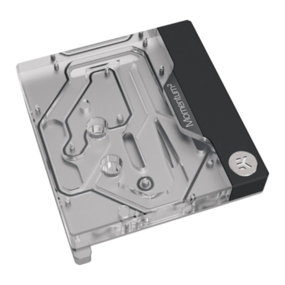
Page 6: Technical Specifications And Water Block Parts
TECHNICAL SPECIFICATIONS AND WATER BLOCK PARTS Technical Specification: - Dimensions: (L x H x W) – 137.5 x 119 x 38.5 mm - D-RGB cable length: 500 mm - D-RGB LED count: 20 - D-RGB connector standard 3-pin (+5V, Data, Blocked, Ground) Position Description Quantity... -
Page 7: Preparing The Motherboard
Save the screws and standoffs for later use. Do not forget to unplug all the LED connectors. Pay attention to the following steps in order to install the EK-Quantum Momentum2 ROG Z690 Extreme D-RGB water block. Always remove the stock cooler and backplate slowly - it might be firmly glued to the motherboard via thermal pads. -
Page 8: Applying Thermal Compound
APPLYING THERMAL COMPOUND STEP 1 Apply the enclosed EK-TIM Ectotherm thermal grease (thermal compound) on the CPU heat spreader – IHS – as shown in the image. The layer of the thermal compound must be thin and even in thickness over the entire surface of the IHS. The excessive or uneven application of thermal grease may lead to poor performance! For this step, you will need:... -
Page 9: Attaching The Water Block
ATTACHING THE WATER BLOCK STEP 1 Carefully place the water block onto the motherboard and align four mounting screws on the motherboard. Hold the water block and the motherboard and turn them upside down. Before placing the Water Block on the motherboard, make sure all the Thermal Pads are placed correctly! (Chapter: Cutting and placing thermal pads). -
Page 10: Attaching The Replacement Cover
STEP 3 After securing the water block, the stored backplate must be attached to the backside of the motherboard using Allen Key 2.5 mm (shown in the picture) or EK-Loop Torque Screwdriver. Start fastening the backplate MAX TORQUE: screws in a cross pattern. Do not tighten fully until all of the nuts are 0.6 Nm ALLEN KEY 2.5 mm partially screwed in. -
Page 11: Fittings And Tubing
FITTINGS AND TUBING STEP 1 With the EK-Quantum Momentum2 ROG Z690 Extreme D-RGB water block, it is mandatory to use the bottom port as the INLET. Mixing the ports may result in poor thermal performance of the water block. OUTLET Tighten the fittings in a clockwise direction until the gasket underneath is compressed. -
Page 12: Testing The Loop
TESTING THE LOOP To make sure the installation of EK components was successful, we recommend you perform a leak test for 24 hours. When your loop is complete and filled with coolant, connect the pump to a PSU outside of your system. Do not connect power to any of the other components. -
Page 13: Support And Service
SUPPORT AND SERVICE In case you need assistance or wish to order spare parts or a new mounting mechanism, please contact: https://www.ekwb.com/customer-support/ For spare parts orders, refer to the page with “TECHNICAL SPECIFICATIONS AND WATER BLOCK PARTS” where you can find the EAN number of each part you might need.
Need help?
Do you have a question about the Momentum2 ROG Maximus Z690 Extreme D-RGB and is the answer not in the manual?
Questions and answers