Advertisement
Quick Links
PD-2610UE
Rear-Mount Customer Display
User Manual
Product Features
Rear-mount VFD customer display for RT series POS terminal
Blue or green screen filter
Two-line display with 20 characters per line
Large character size for easy viewing: 9.03 mm x 5.25 mm
Various command emulation selectable by DIP switch: ADM, Aedex,
ESC/POS, Futaba, Noritake, UTC
12 international character sets support
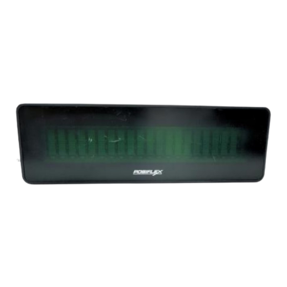
Views of the PD-2610UE
Front View
Display
Rear View
Vents
USB Cable
PD-2610UE Ver. C0
Package Contents
PD-2610UE customer display.........(x1)
System back cover for 2
Fixing screw (#6/32-18L)..............(x2)
Bracket with two Fixing Screw Holes
1
nd
display....(x1)
Vents
DIP Switch Cover
Advertisement

Subscribe to Our Youtube Channel
Related Manuals for POSIFLEX PD-2610UE


Summary of Contents for POSIFLEX PD-2610UE
- Page 1 PD-2610UE Rear-Mount Customer Display User Manual Package Contents PD-2610UE customer display……...(x1) System back cover for 2 display….(x1) Fixing screw (#6/32-18L)…………..(x2) Product Features Rear-mount VFD customer display for RT series POS terminal Blue or green screen filter ...
- Page 2 FCC NOTES This equipment has been tested and found to comply with the limits for a Class A digital device, pursuant to part 15 of the FCC Rules. These limits are designed to provide reasonable protection against harmful interference when the equipment is operated in a commercial environment. This equipment generates, uses, and can radiate radio frequency energy and, if not installed and used in accordance with the instruction manual, may cause harmful interference to radio communications.
-
Page 3: Revision History
Mounting the PD-2610UE onto your POS Terminal Please follow the below instructions to install the customer display onto your RT-series POS terminal. During installation of PD-2610UE, do NOT power ON the terminal. 1. Lay the terminal with its rear facing towards you and tilt the screen all the way down. - Page 4 3. Remove the back cover from your RT-series terminal. Remove Remove the 2 display dummy cover. 5. Pull upwards and remove the top neck cover from the customer display. Remove Pull 6. Remove the bottom neck cover from the Remove customer display.
- Page 5 7. Remove the 3M outer tape from the waterproof rubber cover on the Bracket of the display. 8. Insert the two wedge portions of the display bracket into the wedged grooves of the rear side of the terminal. 9. Check whether the two screw holes of wedge portions of the display bracket align with the two screw holes of the display rear-mount part of the terminal.
- Page 6 10. Fix the customer display to the RT-series terminal with two screws (#6/32- 18L). 11. Place your RT-series terminal screen facing the table. 12. Pull the customer display backwards to the end.
- Page 7 13. Align the two protruding wedges of the bottom neck cover with the two long wedge holes of the display bracket. The two wide gliding tracks on the outsides of the bottom neck cover face the customer display. 14. Insert the two protruding wedges of the bottom neck cover into the two long wedge holes of the display bracket, and push the bottom neck cover toward the base stand of the terminal.
- Page 8 17. Connect the USB cable of PD-2610UE to the USB header of your terminal. 18. Push the display of your terminal forward to the end...
- Page 9 POS terminal, you must determine whether the DIP switch positions 1~2 is properly switched to OFF. If not, please go through the previous section of Setting up the PD-2610UE for Virtual COM Port Mode to complete the necessary DIP switch settings.
- Page 10 DIP switch #1 and #2 are mainly responsible for deciding the interface via which your POS terminal would interact with the customer display. The below table describes four different combinations of DIP switch settings supported by PD-2610UE for your reference. Switch Position USB Class...
- Page 11 Emulation Mode A good range of commands emulation is also provided in PD-2610UE. By setting up DIP switches from #3 to #6 in order according to the below table, you may specify the type of command sets which your pole display will emulate.
- Page 12 EPSON Emulation Mode Command Syntax: Hexadecimal Code Name Hex Code Function Description Move cursor left Move cursor right Move cursor down Move cursor to home position Clear display Move cursor to leftmost position Clear cursor line US MD1 1F 01 Specify overwrite mode US MD2 1F 02...
- Page 13 FUTABA Emulation Mode Command Syntax: Hexadecimal Code Hex Code Function Description Hex Code Function Description Reset Cursor on 04 bb Brightness control Cursor off 1E 0p Change font page Back space 1C 0i International character set 11 09 Horizontal tab 05 0D Moving sign 12 09...
- Page 14 <ESC>uF$ 1B 75 46 Top line 1 time scroll <ESC>uH$ 1B 75 48 Redefine graphic <ESC>uIx<CR> 1B 75 49 x 0D Display fonts <ESC>utcEx 1B 75 74 63 45 x Change d mode <ESC>utcFx 1B 75 74 63 46 x Change RS mode <ESC><RS>*...
-
Page 15: International Character Sets
Spain Germany Japan United Kingdom Norway Denmark I Denmark II Sweden Ex-Jugoslavia Specifications PD-2610UE Display Type Number of Digits 20 digits/row, 2 rows Dot Matrix 5 x 7 dots 9.03 mm Digit Height 5.25 mm Digit Width Blue or green...
Need help?
Do you have a question about the PD-2610UE and is the answer not in the manual?
Questions and answers