Advertisement
Quick Links
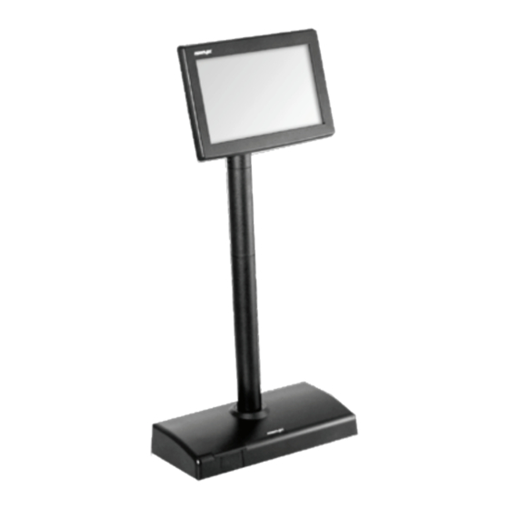
PD-6X07R/ PD-6X07R-AR/
PD-6X07U/ PD-6X07U-AR
Customer Display User Manual
Product Features
Among PD-6X07 series, PD-6X07R/ PD-6X07U are models which
support multiple languages, including English, Traditional Chinese,
Simplified Chinese and Japanese; PD-6X07R-AR/ PD-6X07U-AR are
models with Arabic language support.
7" Graphical customer line display
TFT LCD panel
20 x2, 20 x4, 30 x4 characters support
Adjustable font and background color
JPEG graphics display support
Command emulations support : ADM, Aedex, ESC/POS, Futaba,
Noritake, UTC
Compatibility with Posiflex terminals
Display Model
PD-6207R/ PD-6207R-AR/
PD-6207U/ PD-6207U-AR
PD-6307R/ PD-6307R-AR/
PD-6307U/ PD-6307U-AR
PD-6507R/ PD-6507R-AR/
PD-6507U/ PD-6507U-AR
PD-6607R/ PD-6607R-AR/
PD-6607U/ PD-6607U-AR
19520903020 Ver. A0
http://www.posiflex.com
Package Contents
7" PD-6X07R/ PD-6X07R-AR/ PD-6X07U /
PD-6X07U-AR customer display (x 1)
Stand base for PD-6207 series only (x 1)
RS-232 cable for PD-6X07R/ PD-6X07R-AR
only (x 1)
USB cable for PD-6X07U/ PD-6X07U-AR
only (x 1)
Mounting kits (x 1)
User manual (x 1)
Information CD (x 1)
Posiflex
Any Posiflex terminal
15"/17" KS series terminals
HS series terminals
XT series terminals
1
POS model
Advertisement

Subscribe to Our Youtube Channel
Related Manuals for POSIFLEX PD-6 07R Series


Summary of Contents for POSIFLEX PD-6 07R Series
- Page 1 Adjustable font and background color JPEG graphics display support Command emulations support : ADM, Aedex, ESC/POS, Futaba, Noritake, UTC Compatibility with Posiflex terminals Posiflex Display Model POS model PD-6207R/ PD-6207R-AR/ Any Posiflex terminal PD-6207U/ PD-6207U-AR PD-6307R/ PD-6307R-AR/ 15”/17”...
- Page 2 Views of the PD-6X07 Series PD-6207 Series Stand Base Stand Base Front View Rear View PD-6307 Series Mounting Bracket Front View Rear View PD-6507 Series Mounting Bracket Front View Rear View...
- Page 3 PD-6607 Series Mounting Bracket Front View Rear View View of I/O Interface of PD-6X07R/ PD-6X07R-AR USB-B Type Port 5V DC IN Jack RJ45 Port View of I/O Interface of PD-6X07U/ PD-6X07U-AR USB-B Type Port...
- Page 4 Mounting PD-6207 Series onto POS Terminal Please follow the below instructions to install PD-6207 series customer display onto your POS terminal. During installation, do NOT power ON the terminal. In the example, XT-3000 POS terminal will be used to demonstrate how to complete the installation.
- Page 5 Make sure the other end of USB or RS-232 cable is well connected to the customer display. PD-6207R/ PD-6207R-AR PD-6207U/ PD-6207U-AR The installation of PD-6207R/ PD-6207R-AR/ PD-6207U/ PD-6207U-AR is completed. Tilt up and down the customer display in the direction shown by the arrow. Please do not press on the LCD panel while adjusting the titling angle.
- Page 6 Locate the “Posiflex” sticker at the rear of the terminal. Use a pin tool to tear off the sticker which is used to cover the screw holes. Take L type mounting bracket out of the package. Align the four screw holes of the mounting bracket with the hole pattern at the back of the terminal.
- Page 7 Insert three #6-32-6L fixing screws into the screw holes, and then tighten them to well attach two brackets. Make sure the customer display is well mounted onto your terminal. . Connect USB or RS-232 cable to the POS terminal. If you are the PD-6307R/ PD-6307R-AR user, take the RS-232 cable to attach DB9 connector to the DB9 COM port in the bottom I/O compartment of your terminal.
- Page 8 Mounting PD-6507 Series onto HS series Terminal Please go through below instructions to install PD-6507 series customer display onto Posiflex HS series terminals. During installation, do NOT power ON the terminal. In the example, HS-2208E POS terminal will be used to demonstrate how to complete the installation.
- Page 9 Press down the release tab of top I/O interface cover. Pull the top I/O cover in the direction shown by the arrow in the figure to remove the cover. Position the customer display on a flat surface. While keeping it steady with one hands, pull the rear mounting bracket upright as shown in the figure.
- Page 10 Connect the USB or RS-232 cable to the customer display. If you are the PD-6507R/ PD-6507R-AR user, plug RJ-45 connector of RS-232 cable with the label describing “To PD” into the RJ-45 port of your customer display. For PD-6507U/ PD-6507U-AR models, plug USB Type-B connector of USB cable into the USB port of the customer display.
- Page 11 To keep the cable organized, tuck the extra cable into the I/O compartment and thread the cable through the cable exit as shown in the figure. Cable Exit Push the back cover into place. The installation of PD-6507R/ PD-6507R-AR/ PD-6507U/ PD-6507U-AR is completed. Tilt the display up or down in the direction shown by the arrow.
- Page 12 Positon your terminal with its rear facing toward you. At the edges of the base stand bracket are located two shorter horizontal rails (2) (3) and two longer vertical rails (1) (4), which are used to hold your cable into place.
- Page 13 Insert four #6-32-10L screws into the screws holes and then tighten them to secure the mounting bracket. Have your system sit upright with its rear facing toward you. Connect USB or RS-232 cable to the customer display. If you are the PD-6607R/ PD-6607R-AR user, take RS-232 cable to plug the RJ-45 connector into the RJ-45 port of the customer display.
- Page 14 Push the rails back to the base. If the cable is threaded through the cable passage on the right, by following the sequence number, first slide the shorter rail horizontally and then longer one vertically into place in the direction shown by the arrow to fix your cable into place.
- Page 15 Connect USB or RS-232 cable to the POS terminal. If you are the PD-6607R/ PD-6607R-AR user, have DB9 connector of RS-232 cable attached to the DB9 COM port at the bottom I/O plate of your terminal. For PD-6607U/ PD-6607U-AR models, connect the USB Type-A connector of USB cable to the USB port of your terminal.
- Page 16 PD-6X07R-AR via BIOS To ensure PD-6X07R/ PD-6X07R-AR is able to extract power out of the RS-232 ports of the Posiflex terminals, it is significant to utilize BIOS to manually enable the power output to the serial port which the customer display is connected to before the PD-6X07R/ PD-6X07R-AR could start up.
- Page 17 Installing the Virtual COM Driver for PD-6X07U/ PD-6X07U-AR only Refer to the following steps to install the driver for PD-6X07U/ PD-6X07U-AR models. Connect the USB cable of PD-6X07U/ PD-6X07U-AR to your POS terminal. Locate the SA_PD_LM folder from the “Drivers” folder in the Local Disk (C:) of your POS terminal Double click the USB_VCOM folder.
-
Page 18: Specifications
55 mm ( PD-6507 series) 80 mm ( PD-6607 series) The product information and specifications are subject to change without ※ prior notice. To get the detailed information on PD-6X07R/ PD-6X07R-AR/ PD-6X07U/ PD-6X07U-AR, please check this model from Posiflex Global Website (http://www.posiflex.com/en-global/Download/download). - Page 19 <MEMO>...
- Page 20 <MEMO>...
Need help?
Do you have a question about the PD-6 07R Series and is the answer not in the manual?
Questions and answers