Sign In
Upload
Manuals
Brands
KEB Manuals
Controller
F6 Series
KEB F6 Series Manuals
Manuals and User Guides for KEB F6 Series. We have
2
KEB F6 Series manuals available for free PDF download: Reference Manual, Instructions For Use Manual
KEB F6 Series Reference Manual (321 pages)
ELEVATOR DRIVE
Brand:
KEB
| Category:
Inverter
| Size: 6 MB
Table of Contents
Preface
3
Warning Signs and Symbols
4
More Symbols
5
Laws and Requirements
5
Warranty
6
Support and Liability
6
Copyright
6
Table of Contents
7
List of Figures
14
List of Tables
16
Glossary
17
Standards for Drive Controllers
19
Product Standards Applicable to Drive Controller
19
Basic Standards Referenced by Drive Controller Standards
19
Standards Applicable to Drive Controller Environment
20
Safety Instructions
22
Target Audience
22
General Safety Precautions
23
Installation
25
Start-Up and Operation
26
Maintenance
26
Proper EMC - Compatible Installation
27
Repair
27
Disposal Information
28
Table 2.1 Disposal Contact Information
28
Product Description
29
Specified Application
29
Residual Risks
29
Unintended Use
29
Product Features
30
Model Number
31
Figure 3.1 Model Number
31
Figure 3.2 Nameplate
32
Safety Module
33
Delivered Configuration
33
Supplemental Safety Documentation
34
Control Connections
35
Connection and Control Elements
35
Figure 5.1 Connection and Control Elements
35
Control Terminal Strip X2A
36
Figure 5.2 Assignment of Terminal X2A
37
Motor Monitoring X1C (Temperature, Brake)
38
Specification Brake/Relay Output
38
Figure 5.3 Assignment of X1C
38
Features
39
Description of the Safety I/O
39
Terminal X2B
39
Table 5.1 Assignment of Terminal X2B
39
Assembly of the Wires
40
Safety Status LED
40
Figure 5.4 Assembly of the Terminal X2B
40
Table 5.2 Status LED
41
Encoder Interfaces X3A, X3B
42
Figure 5.5 Assignment of X3A & X3B
42
Encoder Cable Length
43
Description of the Encoder Interfaces
43
Diagnostic Interface X4A
44
Fieldbus Interface X4B
44
Fieldbus Interface X4C
45
Status Leds
45
Boot Display
45
VCC - Led
45
Net St - Led
45
Dev St - Led
46
Opt - Led
46
Method of Control
47
Digital Speed Selection
47
Table 6.1 Digital Speed Selection Inputs
47
Binary Speed Selection
49
Serial Speed Overview
51
DIN66019II Serial Protocol
51
Process Data Overview
52
PDI - Process Data Inputs
52
Figure 6.1 Process Data Inputs & Outputs
52
Control Word (16-Bit)
53
Speed Word (16-Bit, Signed)
53
Table 6.2 Control Word Settings
53
Pre-Torque (16-Bit, Signed)
54
Absolute Target Position
54
Serial Speed DIN66019, Service 49
54
Serial Speed DIN66019, Service 50
55
Process Data Output Address
55
LCD Operator Navigation
56
LCD Operator
56
Figure 7.1 Description of the LCD Operator
56
Operator Keys
57
Figure 7.2 Operator Buttons
57
Navigation
58
Figure 7.3 Basic Navigation Overview
58
Home Screen
59
Program Menu
59
Figure 7.4 Home Screen
59
Figure 7.5 Program Menu
59
Diagnostic Screen
60
Figure 7.6 Diagnostics Screens
60
Figure 7.7 Diagnostic Fault Log Screen
60
Language Screen
61
Figure 7.8 Language Screen Option #1
61
Figure 7.9 Language Screen Option #2
61
Parameter Adjustments
62
Up and down Buttons
62
NUM Function
62
Figure 7.10 NUM Function
62
Changing Settings
63
Password
63
Changing the Password
64
Initial Start-Up
65
Step 1: Connecting to the Drive
65
LCD Operator
65
Drive at Defaulted State (Never Programmed)
65
KEB Elevator Application
65
Combivis
65
Step 2: Programming the Drive
66
Basic Setup
66
Inputs
66
Outputs
66
Motor Data
66
Encoder Data
67
Machine Data
67
Speed Profile
67
Field Bus Configuration
68
Step 3: Learn Procedures
68
Motor Learn
68
Encoder Learn
68
Stationary Pole Identification (SPI)
69
Pole Position Learn
69
Encoder Synchronization
70
Inertia Learn
70
Step 4: Running the Motor
71
Running Inspection
71
Running Automatic
72
Step 5: Ride Quality Adjustments
73
Motor Vibration/Noise Adjustments
73
Encoder Data
73
Control Settings
73
Adjusting S-Curve
74
Rollback Issues
74
Rollback at the Beginning of the Run (no Load Weigher Device)
74
Rollback at the Beginning of the Run (with Load Weigher Device)
75
Rollback at the End of Run
76
Parameter Descriptions
77
Parameter Groups
77
User Definition Parameters (UD)
79
Device Info Parameters (DE)
81
Configuration Handling Parameters (CH)
86
Basic Setup Parameters (US)
92
Table 9.1 US04 Control Type Settings
93
Input Parameters (LI)
96
Table 9.2 LI03 Speed Input Decoding Settings
96
Table 9.3 LI04 Input 1 Function Settings
99
Figure 9.1 MCC Output + Input Connection
101
Figure 9.2 Emergency Slowdown
103
Table 9.4 LI15 Direction Selection Input Settings
107
Table 9.5 LI20 Brake Function Settings
109
Table 9.6 LI50 UPS Mode Settings
110
Motor Data Parameters (LM)
112
Figure 9.3 LM08 Electric Motor Protection Trip Curve
118
Figure 9.4 LM24 Motor Torque Vs. Speed
122
Figure 9.5 LM25 Field Weakening Speed
123
Table 9.7 LM30 Motor Control Settings
125
Encoder Data Parameters (LE)
127
X3A Encoder Input 1
127
Table 9.8 LE03 Swap Encoder 1 Channel Settings
128
X3B Encoder Output / Input 2
134
Machine Data Parameters (LN)
137
Speed Profile Parameters (LS)
139
Run Profiles
139
Figure 9.6 Run Profile Settings
140
Figure 9.7 Jerk Rates
141
Special Function Speeds
144
Preset Profiles
145
Run Profiles
148
High Speed Profile Rate Settings
148
One Floor (Intermediate 1, 2) and NTS Speed Profile Rate Settings
150
Emergency (Intermediate Speed 3) Profile Rate Settings
152
ESD and ETS Profile Rate Settings
154
Figure 9.8 LS49 ESD & ETS Profile Rate
154
Inspection Speed Profile Rate Settings
155
Tune Parameters (LL)
157
Control Setting Parameters (LC)
164
Table 9.9 LC01 Control Mode Setting Descriptions
165
Proportional Gain
166
Integral Gain
168
Integral Offset Gain
170
Figure 9.9 Integral Offset Gain
170
Integral Offset Gain Corner Speeds
173
Figure 9.10 Integral Offset Gain Corner Speeds
173
Table 9.10 LC20 Gain Profile Mode Settings
175
Figure 9.11 LC25 KP High Speed
177
Timer Parameters (LT)
182
Control Sequence (All Services)
184
Special Functions Parameters (LX)
186
Table 9.11 LX13 Speed Following Error Settings
189
Table 9.12 LX21 Unintended Motion Settings
191
Table 9.13 LX23 Encoder Deviation Enable
192
Positioning Parameters (LP)
195
Figure 9.12 High Speed Position Run
196
Figure 9.13 One Floor Position Run
196
Outputs Parameters (LO)
200
Table 9.14 LO05-LO15 Output Function Settings
201
Table 9.15 LO20 Output Function Settings
203
Table 9.16 LO31 Condition 1 Settings
204
Diagnostics Parameters (DG)
206
Table 9.17 F6 Output Status
211
Table 9.18 DG90 System Status Specifications
233
Field Bus Parameters (FB)
235
Processed PDI Data
235
Operations on PDI
237
Serial Communication Setup
239
Process Data Output Addresses
241
Table 9.19 Process Data Output Defaults
241
Process Data Input Addresses
242
Table 9.20 Process Data Input Defaults
242
Process Data Input Function Selection
244
PDO Data
246
PDI Data
247
Special Serial Communication Functions
248
Table 9.21 FB54 RS485 Mode Settings
248
Terminal Slowdown Parameters (TS)
249
Overview
249
Function
249
Figure 9.14 NTS Slowdown Diagram
249
Figure 9.15 NTSD Terminal Slowdown Diagram
250
Figure 9.16 NTSD Timing Diagram
251
Table 9.22 TS01 NTSD Mode Settings
252
NTSD Thresholds and Direction
254
Analog I/O Parameters (LA)
256
Analog Output 1
256
Table 9.23 LA31 Analog Output 1 Function Settings
256
Power Limitation Parameters (PL)
258
Combivis
260
Accessories
260
Combivis Cable Model RS232
260
Figure 10.1 Combivis Cable Model RS232
260
USB-To-Serial Adapter
261
Figure 10.2 USB-To-Serial Adapter
261
USB-To-Serial Converter (DIN + HSP5)
262
Possible Accessory Uses
262
Figure 10.3 USB-To-Serial Converter
262
Combivis Basics (How-To)
263
Differences (F5 to F6)
263
Changing Elevator Parameters
263
Connecting the Cables
263
Changing Parameters on Combivis after Connecting Cable(S)
264
Figure 10.4 Combivis: Open Combivis
264
Figure 10.5 Combivis: Scan for KEB Devices
264
Figure 10.6 Combivis: KEB Device Scan Pop-Up Menu
265
Figure 10.7 Combivis: Add Selected Devices
266
Figure 10.8 Combivis: Node 0
266
Figure 10.9 Combivis: Device Parameters
267
Figure 10.10 Combivis: UD User Definitions
267
Figure 10.11 Combivis: UD01 Password
268
Figure 10.12 Opening Node 0
268
Scoping on Combivis
269
Connecting the Cables
269
Setting up the Scope on Combivis (Online)
269
Figure 10.13 Parameter Name and Number
269
Figure 10.14 Combivis: Opens the Combivis Scope Icon
270
Figure 10.15 Combivis: Create Scope
270
Figure 10.16 Combivis: Define Scope
271
Figure 10.17 Combivis: New Channel
271
Figure 10.18 Combivis: Change Group
272
Figure 10.19 Combivis: Change Parameter
272
Figure 10.20 Combivis: Add Channel
273
Figure 10.21 Combivis: Display Tab
273
Setting up Scope on Combivis (Offline)
274
Figure 10.22 Combivis: Offline Scope Settings
275
Online and Offline Differences
276
Offline Scope Specifications
276
Combivis Upload/Download
276
Required Materials
276
Uploading Parameters (Saving to Computer)
277
Connecting the Cables
277
Figure 10.23 Combivis: Parameter Backup Pop-Up
278
Figure 10.24 Parameter Lists
278
Downloading Parameters
279
Parameter Reference
280
Appendix
315
Certification
315
CE Marking
315
UL Marking
315
EC Type - Examination Certificate Safety Module Type 5
316
Revision History
317
Notes
318
Advertisement
KEB F6 Series Instructions For Use Manual (56 pages)
ELEVATOR DRIVE
Brand:
KEB
| Category:
Controller
| Size: 1 MB
Table of Contents
Preface
3
Signal Words and Symbols
3
More Symbols
4
Laws and Guidelines
4
Warranty and Liability
4
Support
5
Copyright
5
Table of Contents
6
List of Figures
8
List of Tables
9
Basic Safety Instructions
10
Target Group
10
Validity of this Manual
10
Electrical Connection
11
Start-Up and Operation
11
Product Description
12
Specified Application
12
Residual Risks
13
Unintended Use
13
Order Data
13
Table 1: Order Data
13
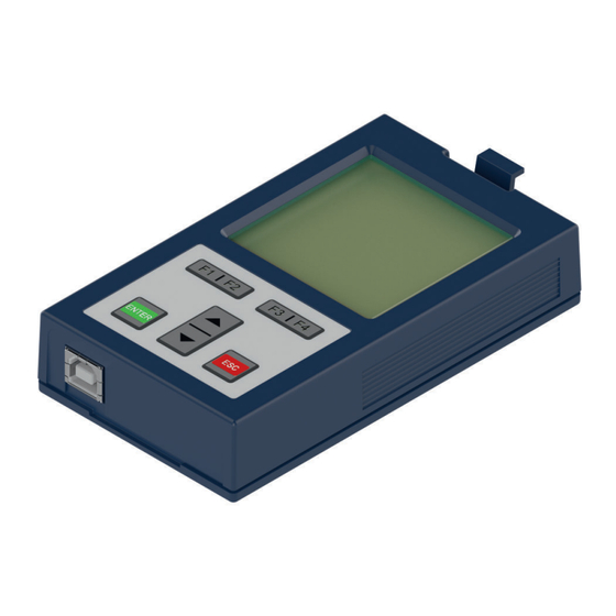
Description of the Operator
14
Figure 1: Description of the Operator
14
Control Card Block Incl. Operator
15
Operating Conditions
15
Figure 2: Control Card Block Incl. Operator (Front Panel)
15
Table 2: Revision Levels of the Housings
15
Interfaces
16
Operator Interface
16
Remote Control
16
Figure 3: D-Sub 9-Pole
16
Diagnostic Interfaces
17
Ethernet Interface
17
USB Interface
17
Figure 4: Ethernet Interface
17
Figure 5: USB Interface
17
Assembly of the Operator
18
Figure 6: Remove the Blind Cover
18
Figure 7: Attach the Operator
19
Navigation
20
Control Elements
20
Description of the Control Elements
20
Menu Bar
20
Function Keys and Function Bar
20
Figure 8: Control Elements
20
Operator Main Menu
21
Switching on
21
Required Files
21
Figure 9: KEB Lift Home Screen
21
Figure 10: Main Menu
21
Table 3: Operator Files
22
Non-Changeable Parameters
23
Figure 11: Non-Changeable Parameters
23
Changeable Parameters
24
Changing with "Up" and "Down
24
Figure 12: Changeable Parameters
24
Selection of Subindices
25
Figure 13: Selection of Subindices
25
Numeric Input
26
Abbreviations in the Function Toolbar
26
Figure 14: Numeric Input
26
Table 4: Abbreviations in the Function Toolbar
26
Inverter Parameters
27
Figure 15: Inverter Parameters
27
Operator Parameters
28
Figure 16: Operator Parameters
28
Figure 17: Operator Parameter Groups
28
Operator System Parameters (OS)
29
Fieldbus Parameters (Fb)
32
Debugging Parameters (Db)
33
Flash File System Parameters (FI)
34
Customer Interface Parameters (CI)
35
Parameter Saving
37
Upload/Download of Parameters
37
Figure 18: Parameter Saving
37
Figure 19: Upload/Download of Parameters
37
Work List
38
File Operations
38
Figure 20: Work List
38
Figure 21: File Operations
38
FTP Mode
39
Function Test of Keyboard and Display
39
Figure 22: FTP Mode
39
Figure 23: Function Test of Keyboard and Display
39
Screen Overview
40
Home and Diagnostic Screens
40
Home and Diagnostic Screen Functionality
40
Figure 24: Home Screen
40
Figure 25: Diagnostic Screen
40
Figure 26: Parameter View Screen
41
Fault Log Screen
42
Language Screen
42
Program Menu
42
Figure 27: Fault Log Screen
42
Figure 28: Language Screen
42
Password Screen
43
Setup Screen
43
Figure 29: Program Menu
43
Figure 30: Password Screen
43
File Menu Screen
44
File Operations
44
Figure 31: Setup Screen
44
Figure 32: File Menu Screen
44
FTP Mode Screen
45
Flash Functions Screen
45
Figure 33: File Operations Screen
45
Figure 34: FTP Mode Screen
45
Figure 35: Flash Functions Screen
45
Upload/Download Screen
46
Figure 36: Upload/Download Screen
46
Default Options Screen
47
Figure 37: Default Options Screens
47
Selecting a New Parameter to Display on the Graphic User Interface (GUI)
48
Figure 38: Parameter Select Screens
49
Screen Navigation
50
Figure 39: Operator Screen Navigation Diagram
50
Figure 40: Diagnostic Screen Navigation Diagram
51
Revision History
52
Notes
53
Advertisement
Related Products
KEB COMBIVERT F5
KEB F5-SERVO
KEB COMBIVERT F6
KEB COMBIVERT F4-C
KEB COMBIVERT F5-G Series
KEB COMBIVERT F5-S Series
KEB COMBIVERT F4-S/1.2
KEB F5 Series
KEB COMBIVERT F5-A
KEB COMBIVERT F5-E
KEB Categories
DC Drives
Controller
Inverter
Control Unit
Industrial Equipment
More KEB Manuals
Login
Sign In
OR
Sign in with Facebook
Sign in with Google
Upload manual
Upload from disk
Upload from URL