Table of Contents
Advertisement
Quick Links
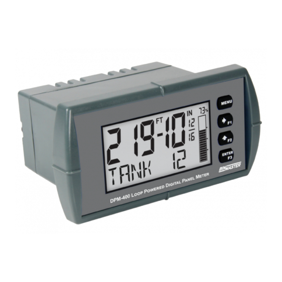
DPM-400 Loop-Powered Meter
Instruction Manual
•
1/8 DIN Loop-Powered Process Meters with NEMA 4X, IP65 Front
•
4-20 mA Input Displayed with ±0.02% FS Accuracy
•
1.5 Volt Drop (4.5 Volt Drop with Backlight)
•
0.7" (17.8 mm) 5 Alphanumeric Characters Top Display
•
0.4" (10.2 mm) 8 Alphanumeric Characters Bottom Display
•
20-Segment Bargraph with Numeric Percent Indication, Optional
•
Shallow Depth Case Extends Only 3.6" (91 mm) Behind Panel
•
(2) Open Collector Outputs Standard; Assigned to Pulse, Alarm, Timer, or Stopwatch
•
(2) Optional Loop-Powered Solid State Relays; Assigned to Alarm, Control, Timer, or Stopwatch
•
Stopwatch & Timer Functions to Drive Relays & Open Collectors
•
Optional Isolated 4-20 mA Analog Output
•
Relay Pump Alternation Based on Level and Runtime
•
Display Relay Runtime & Cycle Count via Relay Info Menu
•
Round Horizontal Tank Function; Just Enter Diameter & Length
•
32-Point Linearization, Square Root Extraction and Programmable Exponent Function
•
Free PC-Based MeterView XL USB Programming Software
•
®
HART
Protocol Transparent
•
Loop-Powered Backlight with Red Backlight for Alarm Conditions
•
Operating Temperature Range: -40 to 167°F (-40 to 75°C)
•
Conformal Coated PCBs for Dust & Humidity Protection
•
Password Protection
•
NEMA 4X Enclosures for up to Ten Meters
•
3-Year Warranty
BINMASTER
Division of Garner Industries LLC
7201 North 98th Street, Lincoln, NE 68507 USA
Tel (800) 278-4241 • Fax: (402) 434-9133
www.binmaster.com
Advertisement
Table of Contents

Related Manuals for BINMASTER DPM-400


Summary of Contents for BINMASTER DPM-400
- Page 1 DPM-400 Loop-Powered Meter Instruction Manual • 1/8 DIN Loop-Powered Process Meters with NEMA 4X, IP65 Front • 4-20 mA Input Displayed with ±0.02% FS Accuracy • 1.5 Volt Drop (4.5 Volt Drop with Backlight) • 0.7" (17.8 mm) 5 Alphanumeric Characters Top Display •...
-
Page 2: Table Of Contents
DPM-400 Digital Panel Meter Instruction Manual Table of Contents Introduction ......................5 Key Features ....................... 6 Ordering Information ..................8 Specifications ....................10 Display ......................10 General ......................10 Input ......................10 Common Open Collector & Relay (Alarm) Specifications ......11 Open Collector Outputs ................ - Page 3 DPM-400 Digital Panel Meter Instruction Manual Advanced Features Menu (ADVANCED) ............34 Advanced Process Variable Setup (ADV PV SETUP) ....... 34 Low-Flow Cutoff (CUTOFF) ................ 35 Noise Filter (FILTER) ................35 Enabling Password Protection (PASSWRD) ..........35 Programmable Function Keys User Menu (USER) ........36 Tare (TARE) ....................
- Page 4 DPM-400 Digital Panel Meter Instruction Manual Table of Figures Figure 1. 1/8 DIN Panel Cutout Dimensions ............14 Figure 2. Panel Mounting Details ................ 14 Figure 3. Meter Dimensions - Side View ............. 16 Figure 4. Meter Dimensions - Front View ............16 Figure 5.
-
Page 5: Introduction
Anyone using this product for such applications These loop-powered meters can be installed virtually does so at his/her own risk. BinMaster shall not anywhere because they get their power from the be held liable for damages resulting from such 4-20 mA loop and therefore require no separate improper use. -
Page 6: Key Features
Instruction Manual Key Features Informative Display Dual-Scale Feature The DPM-400’s display provides multiple ways to help Users can use the dual-scale feature to display users understand and keep track of their processes. the input in two different scales. For instance, the... - Page 7 DPM-400 Digital Panel Meter Instruction Manual Multiple Outputs • Two open collector outputs (standard) • Two solid state relays (optional) • One 4-20 mA output (optional) The open collector outputs and relays generally operate in the same manner, with the major exception...
-
Page 8: Ordering Information
DPM-400 Digital Panel Meter Instruction Manual Ordering Information DPM-400 • Decimal Display/Bargraph Models Model Description 348-0093 Decimal Display, Bargraph, No Options 348-0094 Decimal Display, Bargraph, Two Solid State Relays 348-0095 Decimal Display, Bargraph, 4-20 mA Analog Output 348-0096 Decimal Display, Bargraph, Two Solid State Relays and 4-20 mA Analog Output Note: All models come with two open collector outputs and one digital input standard. - Page 9 DPM-400 Digital Panel Meter Instruction Manual Enclosures Model Description 220-0445 1 Meter Plastic NEMA 4X Enclosure 220-0446 2 Meter Plastic NEMA 4X Enclosure 220-0447 3 Meter Plastic NEMA 4X Enclosure 220-0448 4 Meter Plastic NEMA 4X Enclosure 220-0449 5 Meter Plastic NEMA 4X Enclosure...
-
Page 10: Specifications
DPM-400 Digital Panel Meter Instruction Manual Specifications Max/Min Max/min readings reached by the process are Display stored until reset by the user or until power to the meter is turned off. Except where noted all specifications apply to operation at +25°C. -
Page 11: Common Open Collector & Relay (Alarm) Specifications
DPM-400 Digital Panel Meter Instruction Manual Common Open Collector & Solid State Relays Relay (Alarm) Specifications Rating 250 VAC/VDC @ 1 A resistive 75 VA; 250 VAC; 0.6 A pilot duty Number Two open collectors & two relays (inductive) – UL Code D300... -
Page 12: Meterview Xl Programming Software
DPM-400 Digital Panel Meter Instruction Manual General Compliance MeterView XL Programming Software Information Availability Free download from meter Electromagnetic Compatibility System Microsoft® Windows® 10 & 11 Requirements EMC Emissions • CFR 47 FCC Part 15 Subpart B Class A Communications USB 2.0... -
Page 13: Eu Declaration Of Conformity
DPM-400 Digital Panel Meter Instruction Manual EU Declaration of Conformity Safety Information For shipments to the EU and UK, a Declaration of Conformity is available online at predig.com/docs. • Read complete instructions prior to installation and operation of the meter. -
Page 14: Installation
DPM-400 Digital Panel Meter Instruction Manual Installation There is no need to remove the meter from its case to complete the installation, wiring, and setup of the me- ter for most applications. Unpacking Remove the meter from box. Inspect the packaging and contents for damage. -
Page 15: Meterview Xl Programming Software
Connecting to the Computer to the meter via a USB cable is available for program- DPM-400 series meters may be connected to any ming and setup of the meters. This software greatly Windows 10 or Windows 11 PC via the provided USB... -
Page 16: Dimensions
DPM-400 Digital Panel Meter Instruction Manual Dimensions Connections All units: inches (mm) All connections are made to removable screw terminal connectors located at the rear of the meter. 1.76" (45mm) Connectors Labeling The graphics below show the location of all connect- ors available with requested configuration. -
Page 17: Wiring Diagrams
DPM-400 Digital Panel Meter Instruction Manual Wiring Diagrams 4-20 mA Output Connections Connections for the 4-20 mA transmitter output are made to the connector terminals labeled mA OUT. Current Loop (4-20 mA) Connections The 4-20 mA output must be powered from an exter- Signal connections are made to a six-terminal con- nal power supply. -
Page 18: Setup And Programming
DPM-400 Digital Panel Meter Instruction Manual Setup and Programming Front Panel Buttons and Status LCD Indicators The meter is factory calibrated prior to shipment to display 0.00 to 100.00, which corresponds to the 4-20 mA input. The calibration equipment is traceable to NIST standards. -
Page 19: Display Functions & Messages
DPM-400 Digital Panel Meter Instruction Manual Display Functions & Messages Display Functions & Messages Parameter Action/Setting Description The meter displays various functions and messages during setup, programming, and operation. The following table shows the main menu functions and messages in the order Pascal they appear in the menu. - Page 20 DPM-400 Digital Panel Meter Instruction Manual Display Functions & Messages Display Functions & Messages Parameter Action/Setting Description Parameter Action/Setting Description SOURCE Select PV 2 source (dual-scale only; see PV 2 under advanced Program the meter’s available OUTPUT features menu) outputs...
- Page 21 DPM-400 Digital Panel Meter Instruction Manual Display Functions & Messages Display Functions & Messages Parameter Action/Setting Description Parameter Action/Setting Description Display the PV’s minimum and MIN MAX OC1+2 Hold/un-hold open collector maximum value outputs D mA IN RLY1+2 Display the current mA input value...
- Page 22 DPM-400 Digital Panel Meter Instruction Manual Display Functions & Messages Parameter Action/Setting Description PV+UNIT (1 or 2) Display the process variable and units alternating PV+TAG (1 or 2) Display the process variable and tag alternating TAG+UNIT Display tag and units alternating...
-
Page 23: Main Menu
DPM-400 Digital Panel Meter Instruction Manual Setting Numeric Values Main Menu The numeric values are set using the Right and The main menu consists of all the meter’s programma- Up-Arrow buttons. ble functions: Input, Output, Advanced, and Display. Press Right-Arrow to select next digit and •... -
Page 24: Available Unit Classes And Units
DPM-400 Digital Panel Meter Instruction Manual Available Unit Classes and Units Weight Units (WEIGHT) The meter has six available preprogrammed unit Grams classes: volume, height, temperature, pressure, Kilograms weight, and rate. Each unit class has the following tonnE Tonnes (metric) -
Page 25: Setting The Display Features (Display)
DPM-400 Digital Panel Meter Instruction Manual Display Capabilities Optimization Setting the Display Features (TOP and BOTTOM) (DISPLAY) Display Configuration Examples The meter’s display functions may be programmed The meter’s dual-line display can be setup in multiple using the Display menu. This menu consists of the... -
Page 26: Configuring The Display (Top And Bottom)
TIMER R1 TIMER R2 Programming the Bargraph (BARGRAPH) MIN MAX The DPM-400 comes equipped with a bargraph dis- play for applications where a visual representation of UNITS the process variable’s percentage of full scale is de- sirable. This feature can be enabled or disabled using the Bargraph menu (BARGRAPH). -
Page 27: Programming The Outputs (Output)
DPM-400 Digital Panel Meter Instruction Manual The Open Collector Outputs are programmed in the Programming the Outputs following manner: (OUTPUT) SETUP Depending on the model purchased, the meter may OUTPUT be available with two open collector outputs, two solid state relays, and one 4-20 mA output. The Output OPEN OC. - Page 28 DPM-400 Digital Panel Meter Instruction Manual Alarm (ALARM) For both the PV and digital input alarms, a delay Alarm outputs may be assigned to the PV or the before the alarm is turned on or off may be set, as digital input.
- Page 29 DPM-400 Digital Panel Meter Instruction Manual Timer (TIMER) Stopwatch (STPWATCH) The timer output may be set to generate the timed The stopwatch function may be used to manually run pulse only once (ONESHOT) or continuously (CONT). and control a process for a specific time interval up to 99 hrs., 59 min, and 59 seconds.
-
Page 30: Solid State Relay Outputs (Relay)
DPM-400 Digital Panel Meter Instruction Manual Solid State Relay Outputs (RELAY) Alarm (ALARM) The meter can be optionally equipped with two solid Alarm outputs may be assigned to the PV or the digi- state relays that may be set up for alarms, timer, tal input. - Page 31 DPM-400 Digital Panel Meter Instruction Manual Pump Control (PUMPCTRL) Pump Alternation (ALTERN) The pump control output is used in situations where Pump alternation sets the two relays to alternate the relays are used to control pumps. There are two every time the first on point (ON 1) is reached. The...
- Page 32 DPM-400 Digital Panel Meter Instruction Manual Pump Alternation Example Timer (TIMER) The following is an example application where the re- The timer output may be set to generate the timed lays are programmed for pump alternation. pulse only once (ONESHOT) or continuously (CONT).
-
Page 33: Isolated 4-20 Ma Output (4-20 Ma)
DPM-400 Digital Panel Meter Instruction Manual Isolated 4-20 mA Output (4-20 mA) Stopwatch (STPWATCH) The 4-20 mA menu is used to scale the isolated 4-20 The stopwatch function may be used to manually run mA output based on display values. This menu is not and control a process for a specific time interval up to present on models without a 4-20 mA output option. -
Page 34: Advanced Features Menu (Advanced)
DPM-400 Digital Panel Meter Instruction Manual Advanced Scaling and Advanced Features Menu Calibration (SCALE. C AL) (ADVANCED) This menu offers options to scale or calibrate the To simplify the setup process, functions not needed meter. for most applications are located in the Advanced Features menu. -
Page 35: Low-Flow Cutoff (Cutoff)
DPM-400 Digital Panel Meter Instruction Manual Follow these steps to calibrate the input: Noise Filter (FILTER) The noise filter is available for unusually noisy signals After accessing the SCALE. C AL menu, press that cause an unstable process variable display. The... -
Page 36: Programmable Function Keys User Menu (User)
DPM-400 Digital Panel Meter Instruction Manual Disabling Password Protection To disable password protection, access the Password menu and clear the entered password either by press- ing and holding the Right Arrow button until all digits reset to zero or manually changing all the digits to zero. - Page 37 DPM-400 Digital Panel Meter Instruction Manual Function Keys & Digital Input Display Description Available Settings ALARM. F N Set the function key or digital input to acknowledge an alarm Refer to the following table for descriptions of each available function key or digital input setting.
-
Page 38: Changing System Settings (System)
19. The voltage drop is the same if the back- light is not wired or if it is disabled in the System 2. The display will show 4 mA. The DPM-400 mA menu. output should now be close to 4 mA. Enter the actual value read by the digital mA meter on the second line of the display and press Enter. - Page 39 DPM-400 Digital Panel Meter Instruction Manual Calibrating the Internal mA Reference (ICAL) The Internal Calibration menu is part of the Advanced menu. Internal Calibration is performed as follows: The meter is factory calibrated prior to shipment to display Press the Menu button to enter 0.00 to 100.00, which corresponds to the 4-20 mA input.
-
Page 40: Meter Operation
DPM-400 Digital Panel Meter Instruction Manual Meter Operation Function Keys Operation The meter can accept a 4-20 mA current signal and During operation, the programmable function keys op- display it in engineering units from -9999 to 99999 on erate according to the way they have been pro- grammed in the Advanced Features –... -
Page 41: Runtime & Cycle Count (Info)
DPM-400 Digital Panel Meter Instruction Manual Runtime & Cycle Count (INFO) The relay information menu shows runtime and cycle count for each relay. These values may be cleared at any time by selecting the Clear option (CLEAR?). If the cycle count or runtime values need to be changed... -
Page 42: Troubleshooting
DPM-400 Digital Panel Meter Instruction Manual Troubleshooting Determining Software Version This product is a highly sophisticated instrument with To determine the software (firmware) version of a an extensive list of features and capabilities. If the meter: front panel buttons are used to program the meter, it Press the Menu button to enter can be a difficult task to keep everything straight. -
Page 43: Factory Default Settings
DPM-400 Digital Panel Meter Instruction Manual Factory Default Settings Pump Ctrl On 70.00 The following table shows the factory setting for most Pump Ctrl Off 60.00 of the programmable parameters on the meter. Pump Ctrl On DELAY ON 0 seconds... -
Page 44: Troubleshooting Tips
DPM-400 Digital Panel Meter Instruction Manual Troubleshooting Tips Certain sequences of events can cause unexpected results. To solve these issues, it is best to start fresh from factory defaults and use the manual as a step by step programming guide, rather than a random approach to programming. - Page 45 DPM-400 Digital Panel Meter Instruction Manual Contact BinMaster Technical Support Call: 402.434.9102 Email: support@binmaster.com Sales Support Call: 402.434.9102 Email: info@binmaster.com Place Orders Email: info@binmaster.com For the latest version of this manual please visit www.binmaster.com BINMASTER Division of Garner Industries LLC...
Need help?
Do you have a question about the DPM-400 and is the answer not in the manual?
Questions and answers