Table of Contents
Advertisement
Quick Links
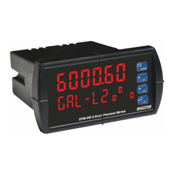
DPM-500 Analog Input Process Meter
Instruction Manual
• 0-20 mA, 4-20 mA, 0-5 V, 1-5 V, and ±10 V Inputs
• Multi-Pump Alternation Control
• Display One Input in Two Different Scales (e.g. Height & Volume)
• Signal Input Conditioning for Flow & Round Horizontal Tank
• 32-Point, Square Root, or Exponential Linearization
• Dual-Line Display
• NEMA 4X and IP65 Rated Front Panel
• UL Listed & CE Marked
• Display Features 0.6
• Six Full Digits on Each Line
• Optional Superluminous Sunlight Readable Display
• Free USB Programming Software & Cable
• 2 or 4 Relays + Isolated 4-20 mA Output Options
• USB, RS-232, & RS-485 Serial Communication Options
• External 4-Relay & Digital I/O Expansion Modules
• Input Power Options Include 85-265 VAC or 12-24 VDC
• Isolated 24 VDC @ 200 mA Transmitter Power Supply
•
Modbus® RTU Communication Protocol Standard
Digits
" & 0.46"
Division of Garner Industries
7201 North 98th Street
Lincoln, NE 68507-9741
(402) 434-9102
Process Meter
Advertisement
Table of Contents
Troubleshooting

Related Manuals for BINMASTER DPM-500


Summary of Contents for BINMASTER DPM-500
- Page 1 DPM-500 Analog Input Process Meter Instruction Manual Process Meter • 0-20 mA, 4-20 mA, 0-5 V, 1-5 V, and ±10 V Inputs • Multi-Pump Alternation Control • Display One Input in Two Different Scales (e.g. Height & Volume) • Signal Input Conditioning for Flow & Round Horizontal Tank •...
- Page 2 Limited Warranty BinMaster warrants this product against defects in material or workmanship for the specified period under “Specifications” from the date of shipment from the factory. BinMaster’s liability under this limited warranty shall not exceed the purchase value, repair, or replacement of the defective unit.
-
Page 3: Table Of Contents
DPM-500 Analog Input Meter Instruction Manual Table of Contents Table of Contents ----------------------------------------- 3 Relay and Alarm Operation Diagrams ------------------- 27 High Alarm Operation (Set > Reset) ---------------------- 27 Table of Figures ------------------------------------------- 4 Low Alarm Operation (Set < Reset)----------------------- 27 Introduction ------------------------------------------------- 4 High Alarm with Fail-Safe Operation (Set >... -
Page 4: Table Of Figures
4-20 mA output option. A digital input is standard. A fully loaded DPM-500 meter has the following: four SPDT relays, 4-20 mA output, and two 24 VDC power supplies. The meter’s capabilities may be enhanced by adding the following external... - Page 5 DPM-500 Analog Input Meter Instruction Manual Sunlight Readable Display Models Model Number Reorder Model Power Options Installed PD6000-6H0-BM 348-0077 85-265 VAC No options PD6000-6H2-BM 348-0078 85-265 VAC 2 relays PD6000-6H3-BM 348-0079 85-265 VAC 4-20 mA output PD6000-6H4-BM 348-0080 85-265 VAC...
-
Page 6: Specifications
DPM-500 Analog Input Meter Instruction Manual Specifications Except where noted all specifications apply to operation at +25°C. Environmental Operating temperature range: -40 to 65°C General Storage temperature range: -40 to 85°C Relative humidity: 0 to 90% non-condensing Display Line 1: 0.60" (15 mm) high, red LEDs Line 2: 0.46"... -
Page 7: Relays
DPM-500 Analog Input Meter Instruction Manual F4 Digital Input Logic High: 3 to 5 VDC Isolated 4-20 mA Transmitter Output Logic Levels Logic Low: 0 to 1.25 VDC Output Source Process variable (PV), max, min, set points 1-8, Relays Modbus input, or manual control mode Scaling Range 1.000 to 23.000 mA for any display range... -
Page 8: Compliance Information
Voltage Interruptions <5%V for 250 periods Note: Testing was conducted on DPM-500 meters installed through the covers of grounded metal enclosures with cable shields grounded at the point of entry representing installations designed to optimize EMC performance. Declaration of Conformity available at www.binmaster.com... -
Page 9: Safety Information
DPM-500 Analog Input Meter Instruction Manual Safety Information CAUTION: Read complete WARNING: Risk of electric instructions prior to installation shock or personal injury. and operation of the meter. Hazardous voltages exist within enclosure. Installation and service should be performed only by trained service personnel. -
Page 10: Mounting Dimensions
DPM-500 Analog Input Meter Instruction Manual Mounting Dimensions Figure 3. Meter Dimensions - Side View Figure 4. Meter Dimensions - Top View Transmitter Supply Voltage Selection (P+, P-) All meters, including models equipped with the 12-24 VDC power option, are shipped from the factory configured to provide 24 VDC power for the transmitter or sensor. -
Page 11: Connections
M-LINK connector. Otherwise damage will occur to the Warning! equipment and the meter. Figure 6. Connector Labeling for Fully Loaded DPM-500 Power Connections Power connections are made to a two-terminal connector labeled POWER on Figure 6 on page 11. The meter will operate regardless of DC polarity connection. -
Page 12: Signal Connections
DPM-500 Analog Input Meter Instruction Manual Signal Connections Signal connections are made to a six-terminal connector labeled SIGNAL on Figure 6. The COM (common) terminal is the return for the 4-20 mA and the 10 V input signals. Current (mA) Connections The following figures show examples of current connections. -
Page 13: Modbus Rtu Serial Communications
Serial communications connection is made to an RJ45 connector labeled M-LINK on Figure 6. For interfacing to the DPM-500, use the PDA1232 for RS-232 or the PDA1485 for RS-485. The same port is used for interfacing with all expansion modules (e.g. external relays, digital I/O). -
Page 14: F4 Digital Input Connections
DPM-500 Analog Input Meter Instruction Manual F4 Digital Input Connections A digital input, F4, is standard on the meter. This digital input is connected with a normally open contact across F4 and COM, or with an active low signal applied to F4. -
Page 15: External Relays & Digital I/O Connections
DPM-500 Analog Input Meter Instruction Manual External Relays & Digital I/O Connections The relay and the digital I/O expansion modules PDA1004 & PDA1044 are connected to the meter using a CAT5 cable provided with each module. The two RJ45 connectors on the expansion modules are identical and interchangeable;... -
Page 16: Setup And Programming
DPM-500 Analog Input Meter Instruction Manual Setup and Programming The meter is factory calibrated prior to shipment to read in milliamps and volts depending on the input selection. The calibration equipment is traceable to NIST standards. Overview There are no jumpers to set for the meter input selection. -
Page 17: Meterview Pro Software
DPM-500 Analog Input Meter Instruction Manual ® MeterView Pro Software The meter can also be programmed using the PC-based MeterView Pro software included with the meter. This software can be installed on any Microsoft® Windows® (XP/Vista/7/8/10) computer by connecting the meter’s onboard USB. The meter is powered by the USB connection, so there is no need to wire anything prior to programming the meter, though USB is intended only for meter configuration. -
Page 18: Display Functions & Messages
DPM-500 Analog Input Meter Instruction Manual Display Functions & Messages The meter displays various functions and messages during setup, programming, and operation. The following table shows the main menu functions and messages in the order they appear in the menu. -
Page 19: Main Menu
DPM-500 Analog Input Meter Instruction Manual Display Parameter Action/Setting Description Display Parameter Action/Setting Description Rst Hi Reset high Press Enter to reset max pass Password Enter the Password menu display Pass 1 Password 1 Set or enter Password 1 Rst Lo... -
Page 20: Setting Up The Meter (Setup)
DPM-500 Analog Input Meter Instruction Manual Setting Up the Meter (setup) The Setup menu is used to select: 1. Input signal the meter will accept 2. Dual-scale feature for some level applications 3. Select the display Note: Use the d-SCAL selection... -
Page 21: Setting The Input Units Or Custom Tags (Units)
DPM-500 Analog Input Meter Instruction Manual Setting the Input Units or Custom Tags (units) Enter the input unit or custom tag that will be displayed if d unit is selected as the line 2 parameter. See the flow chart on page 25 to access the display menu to show the unit or tag on display line 2. The... -
Page 22: Programming The Meter (Prog)
Use the Calibrate menu to apply a signal from a calibrator or a flowmeter. • The DPM-500 is a single input meter with dual-scale capability. The Program menu contains the Scale and the Calibrate menus. Note: The Scale and Calibrate functions are exclusive of each other. The meter uses the last function programmed. - Page 23 DPM-500 Analog Input Meter Instruction Manual Scaling the Meter (SCALE) The process input (4-20 mA, 10 VDC) can be scaled to display the process variable in engineering units. A signal source is not needed to scale the meter; simply program the inputs and corresponding display values.
- Page 24 DPM-500 Analog Input Meter Instruction Manual Calibrating the Meter with External Source (Cal) Note: To scale the meter without a signal source refer to Scaling the Meter (SCALE), page 23. The meter can be calibrated to display the process variable in engineering units by applying the appropriate input signal and following the calibration procedure.
-
Page 25: Setting The Display Parameter & Intensity (Dsplay)
DPM-500 Analog Input Meter Instruction Manual Setting the Display Parameter & Intensity (dsplay) The main display (Line 1) can be programmed to display: 1. Process value 1 (PV1) 2. Process value 2 (PV2) 3. Percent of PV1 (PCT) 4. Relay set points 5. -
Page 26: Setting The Relay Operation (Relay)
DPM-500 Analog Input Meter Instruction Manual Setting the Relay Operation (relay) This menu is used to set up the operation of the relays. During setup, the relays do not follow the input and they will remain in the state found prior to entering the Relay menu. -
Page 27: Setting Fail-Safe Operation
DPM-500 Analog Input Meter Instruction Manual Setting Fail-Safe Operation In fail-safe mode of operation, the relay coil is energized when the process variable is within safe limits and the relay coil is de-energized when the alarm condition exists. The fail-safe operation is set independently for each relay. -
Page 28: High Alarm With Fail-Safe Operation (Set > Reset)
DPM-500 Analog Input Meter Instruction Manual High Alarm with Fail-Safe Low Alarm with Fail-Safe Operation Operation (Set > Reset) (Set < Reset) Note: Relay coil is energized in non-alarm Note: Relay coil is energized in non-alarm condition. In case of power failure, relay will condition. -
Page 29: Pump Alternation Control Operation
DPM-500 Analog Input Meter Instruction Manual Pump Alternation Control Operation Relay Sampling Operation Input Reset Sample Sample Sample Time Time Time Relay When the signal crosses the set point, the relay trips and the sample time starts. After the sample time has elapsed, the relay resets. -
Page 30: Signal Loss Or Loop Break Relay Operation
DPM-500 Analog Input Meter Instruction Manual Signal Loss or Loop Break Relay Operation The following graph shows the loop break relay operation for a high alarm relay. Input Reset de-energized energized Relay Loop Break = Ignore Relay Loop Break = Off... -
Page 31: Relay Operation Details
DPM-500 Analog Input Meter Instruction Manual Relay Operation Details Overview The relay capabilities of the meter expand its usefulness beyond simple indication to provide users with alarm and control functions. These capabilities include front panel alarm status LEDs as well as either 2 or 4 optional internal relays and/or 4 external relays expansion module. -
Page 32: Latching And Non-Latching Relay Operation
DPM-500 Analog Input Meter Instruction Manual Latching and Non-Latching Relay Operation The relays can be set up for latching (manual reset) or Relay terminology for following tables non-latching (automatic reset) operation. Terminology Relay Condition Alarm (Tripped) The On and Off terminology does not refer to the status of Normal (Reset) the relay’s coil, which depends on the fail-safe mode... -
Page 33: Acknowledging Relays
DPM-500 Analog Input Meter Instruction Manual Acknowledging Relays There are two ways to acknowledge relays programmed for manual reset: 1. Via the programmable front panel function keys F1-F3 (Default: F3 assigned to ACK). 2. Remotely via a normally open pushbutton wired across one of the digital inputs and the +5 V terminals on the digital I/O modules, or using the F4 digital input, which is triggered with a contact closure to COM, or with an active low signal (see page 14). - Page 34 DPM-500 Analog Input Meter Instruction Manual Application #2: Pump Alternation Using Relays 3 & 4 1. Relays 1 and 2 are set up for low and high alarm indication. 2. Relays 3 and 4 are set up for pump alternation.
-
Page 35: Setting Up The Interlock Relay (Force On) Feature
DPM-500 Analog Input Meter Instruction Manual Setting Up the Interlock Relay (Force On) Feature Relays 1-4 can be set up as interlock relays. To set up the relays for the interlock feature: 1. Access the Setup – Relay – Action menu and set the action to off. -
Page 36: Reset Menu (Reset)
DPM-500 Analog Input Meter Instruction Manual Reset Menu (reset) The Reset menu is used to reset the maximum or minimum reading (peak or valley) reached by the process; both may be reset at the same time by selecting “reset high & low” (rst HL). The tare value used to zero the display may be reset by selecting “reset tare”... -
Page 37: Making Changes To A Password Protected Meter
DPM-500 Analog Input Meter Instruction Manual Making Changes to a Password Protected Meter If the meter is password protected, the meter will display the message Locd (Locked) when the Menu button is pressed. Press the Enter button while the message is being displayed and enter the correct password to gain access to the menu. -
Page 38: Advanced Features Menu
DPM-500 Analog Input Meter Instruction Manual Advanced Features Menu To simplify the setup process, functions not needed for most applications are located in the Advanced Features menu. Press and hold the Menu button for three seconds to access the advanced features of the meter. -
Page 39: Noise Filter (Filter)
DPM-500 Analog Input Meter Instruction Manual Display Parameter Action/Setting Display Parameter Action/Setting 20 nmA C CAL 20 mA output Enter mA output value Current Calibrate 4-20 mA current read by milliamp meter calibration input (internal reference with at least 0.001 mA... -
Page 40: Modbus Rtu Serial Communications (Serial)
Note: More detailed instructions are provided with each optional serial communications adapter. Note: Refer to the Modbus Register Tables located at www.binmaster.com for details. When using more than one meter in a multi-drop mode, each meter must be provided with its own unique address. -
Page 41: Signal Input Conditioning (Functn)
DPM-500 Analog Input Meter Instruction Manual Signal Input Conditioning (Functn) The Function menu is used to select the signal input conditioner applied to the input: linear, square root, programmable exponent, or round horizontal tank volume calculation. The multi-point linearization is part of the linear function selection. -
Page 42: Low-Flow Cutoff (Cutoff)
DPM-500 Analog Input Meter Instruction Manual Changing the Volume from Gallons to Liters In the above graphic, entering the 48" for the diameter and 120" for the length of the round horizontal tank, the meter automatically calculates that the volume of the tank is 940.02 gallons. -
Page 43: Tare (Tare)
DPM-500 Analog Input Meter Instruction Manual Function Keys & Digital I/O Available Settings Refer to the following table for descriptions of each available function key or digital I/O setting. Display Description Display Description Ln1 HL Rst Hi Display maximum & minimum... -
Page 44: Internal Source Calibration (Ical)
DPM-500 Analog Input Meter Instruction Manual Internal Source Calibration (ICAL) The meter is factory calibrated prior to shipment to read in milliamps and volts depending on the input selection. The calibration equipment is traceable to NIST standards. The use of calibrated signal sources is necessary to calibrate the internal source of the meter. The meter’s internal source is what allows the user to scale the meter without applying a signal. -
Page 45: Meter Operation
DPM-500 Analog Input Meter Instruction Manual Meter Operation The meter is capable of accepting current (0-20 mA, 4-20 mA) and voltage signals (0-5 V, 1-5 V, 0-10 V, 10 V) and displaying these signals in engineering units from -99999 to 999999 (e.g. a 4-20 mA signal could be displayed as -50.000 to 50.000). -
Page 46: Troubleshooting
DPM-500 Analog Input Meter Instruction Manual Troubleshooting The rugged design and the user-friendly interface of the meter should make it unusual for the installer or operator to refer to this section of the manual. However, due to the many features and functions of the meter, it’s possible that the setup of the meter does not agree with what an operator expects to see. -
Page 47: Factory Defaults & User Settings
DPM-500 Analog Input Meter Instruction Manual Factory Defaults & User Settings The following table shows the factory setting for most of the programmable parameters on the meter. Parameter Display Default Setting Parameter Display Default Setting Input Off 3 Off delay relay 3 0.0 sec... -
Page 48: Troubleshooting Tips
DPM-500 Analog Input Meter Instruction Manual Troubleshooting Tips Symptom Check/Action No display at all Check power at power connector Not able to change setup or Meter is password-protected, enter correct six-digit programming, Locd is displayed password to unlock Check: Meter displays error message during 1. -
Page 49: Eu Declaration Of Conformity
EU Declaration of Conformity Issued in accordance with ISO/IEC 17050-1:2004. Precision Digital Corporation 233 South Street Hopkinton, MA 01748 USA as the manufacturer, declare under our sole responsibility that the product(s), Model PD6000 Series Process Meter to which this declaration relates, is in conformity with the European Union Directives shown below: 2014/35/EU Low Voltage Directive... - Page 50 DPM-500 Analog Input Meter Instruction Manual Division of Garner Industries 7201 N. 98th St. P.O. Box 29709 Lincoln, NE 68507 Lincoln, NE 68529 (402) 434-9102 Fax: (402) 434-9133 www.binmaster.com Email: info@binmaster.com 925-0365 LIM6000BM_A SFT039 Ver 4.010 & up 09/18...
Need help?
Do you have a question about the DPM-500 and is the answer not in the manual?
Questions and answers