BINMASTER NCR-86 Operating Instructions Manual
Radar sensor for continuous level measurement of liquids and bulk solids
Hide thumbs
Also See for NCR-86:
- Quick start manual (2 pages) ,
- Quick setup manual (28 pages) ,
- Operating instructions manual (140 pages)

Subscribe to Our Youtube Channel
Related Manuals for BINMASTER NCR-86


Summary of Contents for BINMASTER NCR-86
- Page 1 Operating Instructions Radar sensor for continuous level measurement of liquids and bulk solids NCR-86 Two-wire 4 … 20 mA/HART Document ID: 1031453...
-
Page 2: Table Of Contents
Measured value indication - Selection of national language .......... 51 Parameter adjustment ....................52 Save parameter adjustment data ................... 73 Set up with Smartphone/tablet ..................... 74 Preparations ........................74 Connecting ........................74 Parameter adjustment ....................75 10 Menu overview ........................76 NCR-86 • Two-wire 4 … 20 mA/HART... - Page 3 15 Supplement ..........................97 15.1 Technical data ........................ 97 15.2 Radio astronomy stations .....................119 15.3 Dimensions ........................119 15.4 Licensing information for open source software ............136 15.5 Trademark ........................136 Editing status: 2024-02-28 NCR-86 • Two-wire 4 … 20 mA/HART...
-
Page 4: About This Document
The dot set in front indicates a list with no implied sequence. Sequence of actions Numbers set in front indicate successive steps in a procedure. Disposal This symbol indicates special instructions for disposal. NCR-86 • Two-wire 4 … 20 mA/HART... -
Page 5: For Your Safety
During work on and with the device, the required personal protective equipment must always be worn. Appropriate use NCR-86 is a sensor for continuous level measurement. You can find detailed information about the area of application in chapter "Product description". Operational reliability is ensured only if the instrument is properly used according to the specifications in this document as well as pos- sible supplementary instructions. -
Page 6: Mode Of Operation - Radar Signal
Installations in Canada shall comply with the relevant requirements of the Canadian Electrical Code (CEC Part I) (Canada). A Class 2 power supply unit has to be used for the installation in the USA and Canada. NCR-86 • Two-wire 4 … 20 mA/HART... -
Page 7: Product Description
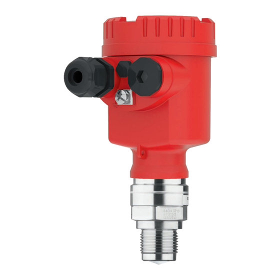
Constituent parts Fig. 1: Components of NCR-86 Radar antenna 2 Process fitting Process seal Electronics housing Housing cover with optional display and adjustment module Ventilation Use see chapter "Mounting instructions, sealing to the process" NCR-86 • Two-wire 4 … 20 mA/HART... -
Page 8: Principle Of Operation
Documents and software Further information can be found on our homepage. There you will find the documentation and further information about the device. Principle of operation Application area The NCR-86 is a radar sensor for continuous level measurement of liquids as well as bulk solids under different process conditions. Antenna systems The instrument is available with different antenna systems: NCR-86 • Two-wire 4 … 20 mA/HART... -
Page 9: Adjustment
The housing with display and adjustment unit can be rotated by 360° for optimum readability and operability. Wireless adjustment Devices with integrated Bluetooth module can be adjusted wirelessly via smartphone/tablets (iOS or Android operating system). NCR-86 • Two-wire 4 … 20 mA/HART... -
Page 10: Packaging, Transport And Storage
Technical data - Ambient conditions" • Relative moisture 20 … 85 % Lifting and carrying With instrument weights of more than 18 kg (39.68 lbs) suitable and approved equipment must be used for lifting and carrying. NCR-86 • Two-wire 4 … 20 mA/HART... -
Page 11: Setup - The Most Important Steps
Adjustment app Parameterize sensor Liquids Bulk solids Enter medium type, application, vessel height, adjustment and mode 100% 100% Check measured value Indicators Output Download via Apple App Store, Google Play Store, Baidu Store NCR-86 • Two-wire 4 … 20 mA/HART... -
Page 12: Mounting
• Abrasion and mechanical influences Second Line of Defense As a standard feature, the NCR-86 is separate from the process through its plastic antenna encapsulation. Optionally, the instrument is available with a Second Line of Defense (SLOD), a second process separation. It is located as gas-tight leadthrough between the process component and the electronics. - Page 13 Plastic double chamber Aluminium - double chamber Housing orientation The housing of NCR-86 can be rotated completely by 360°. This enables optimal reading of the display and easy cable entry. For housings made of plastic or electropolished stainless steel, this is done without tools.
- Page 14 1. Screw the housing cover on tightly by hand 2. Unscrew the locking screw from the cover up to the stop using a size 4 hexagonal spanner 3. Check if the cover can no longer be turned NCR-86 • Two-wire 4 … 20 mA/HART...
-
Page 15: Mounting Preparations, Mounting Strap
• Single chamber housing – Inclination in three steps 0°, 90° and 180° – Inclination 180° steplessly • Double chamber housing – Inclination in two steps 0° and 90° – Inclination 90° steplessly NCR-86 • Two-wire 4 … 20 mA/HART... -
Page 16: Mounting Versions, Plastic Horn Antenna
Mounting strap - Ceiling The instrument is normally mounted vertically with a bracket on the mounting ceiling. This allows swivelling the sensor up to 180° for optimal orientation and rotating for optimal connection. NCR-86 • Two-wire 4 … 20 mA/HART... - Page 17 Fig. 11: Wall mounting horizontally via the mounting strap with length 170 mm Fig. 12: Wall mounting with inclined wall via the mounting strap with length 300 mm Flange Two versions are available for mounting the instrument on a nozzle: NCR-86 • Two-wire 4 … 20 mA/HART...
-
Page 18: Mounting Instructions
It is permanently connected with the radar sensor and sealed. Fig. 14: Adapter flange Connection screw 2 Adapter flange Process seal Mounting instructions Polarisation Radar sensors for level measurement emit electromagnetic waves. The polarisation is the direction of the electrical share of these waves. It is identifiable by a mark on the housing, see the following drawing: NCR-86 • Two-wire 4 … 20 mA/HART... - Page 19 (7.874 in) from the vessel wall. If the device is installed in the center of dished or round vessel tops, multiple echoes can arise. However, these can be suppressed by an appropriate adjustment (see chapter "Setup"). NCR-86 • Two-wire 4 … 20 mA/HART...
- Page 20 Mount the instrument at least 200 mm (7.874 in) away from the ves- solids sel wall. In this case, it is recommended to repeat the false signal suppression at a later time with existing buildup. NCR-86 • Two-wire 4 … 20 mA/HART...
- Page 21 This applies especially if buildup on the vessel wall is to be expected. Reference plane The measuring range of the NCR-86 physically begins with the antenna end. However, the min./max. adjustment begins mathematically with the reference plane, which is located differently depending on the sensor version.
- Page 22 Flange connection 5 Hygienic fitting Horn antenna Flange with lens antenna Inflowing medium - liq- Do not mount the instrument in or above the filling stream. Make uids sure that you detect the medium surface, not the inflowing product. Fig. 20: Mounting of the radar sensor with inflowing medium Inflowing medium - bulk As a general rule, the device must not be mounted too close to or solids above the inflowing medium, otherwise the radar signal could be disturbed. NCR-86 • Two-wire 4 … 20 mA/HART...
- Page 23 5 Mounting Silo with filling from top: The optimal mounting position is opposite the filling aperture. To avoid heavy soiling of the antenna, the distance to any filter or dust exhauster should be as large as possible. Fig. 21: Mounting of the radar sensor with inflowing medium – filling from top Silo with lateral filling: The optimal mounting position is next to the filling. To avoid heavy soiling of the antenna, the distance to any filter or dust exhauster should be as large as possible. NCR-86 • Two-wire 4 … 20 mA/HART...
- Page 24 Socket mounting - short For nozzle mounting, the nozzle should be as short as possible and nozzles its end rounded. This reduces false reflections from the nozzle. With threaded connection, the antenna end should protrude at least 5 mm (0.2 in) out of the nozzle. NCR-86 • Two-wire 4 … 20 mA/HART...
- Page 25 Flange with lens antenna Socket mounting - longer If the reflective properties of the medium are good, you can mount nozzles NCR-86 on sockets longer than the antenna. The socket end should be smooth and burr-free, if possible also rounded. Note: When mounting on a longer socket piece, we recommend to carry out a false signal suppression (see chapter "Parameter adjustment").
- Page 26 Thread with integrated antenna system Socket diameter "d" Socket length "h" 40 mm 1½" ≤ 150 mm ≤ 5.9 in 50 mm 2" ≤ 200 mm ≤ 7.9 in 80 mm 3" ≤ 300 mm ≤ 11.8 in 100 mm 4" ≤ 400 mm ≤ 15.8 in 150 mm 6" ≤ 600 mm ≤ 23.6 in NCR-86 • Two-wire 4 … 20 mA/HART...
- Page 27 PTFE washer Antenna encapsulation Note: PTFE-plated flanges, however, have a preload loss over time with large temperature changes. This can negatively the sealing proper- ties. To avoid this, use the disc springs from the scope of delivery during mounting. They fit the required flange screws. Proceed as follows to seal effectively: 1. Use flange screws according to the number of flange holes NCR-86 • Two-wire 4 … 20 mA/HART...
- Page 28 G1½ G1½ SW 65 SW 60 (2.56") (2.36") G1½A Fig. 27: NCR-86 with PTFE threaded adapter (example NCR-86 with thread G1½) Sensor O-ring seal (sensor side) PTFE threaded adapter Flat seal (process side) Welded socket NCR-86 • Two-wire 4 … 20 mA/HART...
- Page 29 Fig. 28: Mounting the instrument on insulated vessels Vessel insulation Distance piece for temperature decoupling Electronics housing Vessel installations The mounting location of the radar sensor should be a place where no other equipment or fixtures cross the path of the radar signals. NCR-86 • Two-wire 4 … 20 mA/HART...
- Page 30 Fig. 30: Alignment in liquids Orientation - Bulk solids In a cylindrical silo with conical outlet, the mounting is carried out on a third up to the half of the vessel radius from outside (see following drawing). NCR-86 • Two-wire 4 … 20 mA/HART...
- Page 31 Alternatively, the angle of inclination can be determined using the fol- lowing drawing and table. It depends on the measuring distance "d" and the distance "a" between vessel centre and mounting position. Check the alignment with a suitable level or water level. NCR-86 • Two-wire 4 … 20 mA/HART...
- Page 32 5 Mounting Fig. 32: Determination of the angle of inclination for alignment of NCR-86 Distance d (m) 2° 4° 6° 8° 10° 10.5 12.2 11.1 13.9 12.5 15.6 10.5 13.9 17.4 NCR-86 • Two-wire 4 … 20 mA/HART...
- Page 33 3. Re-tighten the terminal screws, max. torque see chapter "Techni- cal data". Agitators Agitators in the vessel can reflect the measurement signal and thus lead to undesired incorrect measurements. Note: To avoid this, a false signal suppression should be carried out with the agitators in motion. This ensures that the interfering reflections from the agitators are saved with the blades in different positions. NCR-86 • Two-wire 4 … 20 mA/HART...
- Page 34 In these applications, it must be taken into account that the radar sensors are designed for relatively slow level changes. Therefore, when using on moving parts, observe the measurement characteris- tics of the device (see chapter "Technical data"). NCR-86 • Two-wire 4 … 20 mA/HART...
- Page 35 The sensor should be directed towards the emptying point in the centre of the silo. This can be done, for example, using the mounting strap. Fig. 36: Installation and orientation in multiple chamber silos NCR-86 • Two-wire 4 … 20 mA/HART...
- Page 36 To protect the device against buildup, particularly in case of strong condensation, air rinsing is recommended. Plastic horn antenna: The NCR-86 with plastic horn antenna is optionally available with a rinsing air connection. The mechanical configuration differs accord- ing to the flange version, see following graphics. Fig. 38: Plastic horn antenna with compression flange Rinsing air connection NCR-86 •...
-
Page 37: Measuring Rigs - Bypass
A bypass consists of a standpipe with lateral process fittings. It is at- pass tube tached to the outside of a container as a communicating vessel. The NCR-86 in 80 GHz technology is suitable as standard for non- contact level measurement in such a bypass. NCR-86 • Two-wire 4 … 20 mA/HART... - Page 38 • The measurement through a ball valve with unrestricted channel is possible • The deviation can increase in the area of the connecting tube to the container ± 200 mm NCR-86 • Two-wire 4 … 20 mA/HART...
-
Page 39: Measurement Setup - Flow
• Rectangular weir broad crown (ISO 3846) Flow formula: If the flow formula of your flume is known, you should select this op- tion, as the accuracy of the flow measurement is highest here. • Flow formula: Q = k x h The value given takes into account the block distance. At smaller distances, the measuring accuracy is reduced, see "Technical data". NCR-86 • Two-wire 4 … 20 mA/HART... - Page 40 Detailed project planning data can be found at the channel manufac- turers and in the technical literature. The following examples serve as an overview for flow measurement. Rectangular overfall 3 ... 4 h 90° 90° Fig. 42: Flow measurement with rectangular flume: h = max. filling of the max. rectangular flume 1 Overfall orifice (side view) Upstream water Tailwater 4 Overfall orifice (view from tailwater) NCR-86 • Two-wire 4 … 20 mA/HART...
- Page 41 5 Mounting Khafagi-Venturi flume 3 ... 4 x h 90° Fig. 43: Flow measurement with Khafagi-Venturi flume: h = max. filling of max. the flume; B = tightest constriction in the flume Position sensor 2 Venturi flume NCR-86 • Two-wire 4 … 20 mA/HART...
-
Page 42: Connecting To Power Supply
In the case of instrument housings with self-sealing NPT threads, it is not possible to have the cable entries screwed in at the factory. The free openings for the cable glands are therefore covered with red dust protection caps as transport protection. NCR-86 • Two-wire 4 … 20 mA/HART... -
Page 43: Connecting
4. Remove approx. 10 cm (4 in) of the cable mantle, strip approx. 1 cm (0.4 in) of insulation from the ends of the individual wires 5. Insert the cable into the sensor through the cable entry NCR-86 • Two-wire 4 … 20 mA/HART... -
Page 44: Wiring Plan, Single Chamber Housing
10. Reinsert the display and adjustment module, if one was installed 11. Screw the housing lid back on The electrical connection is finished. Wiring plan, single chamber housing The following illustration applies to the non-Ex as well as to the Ex ia version. NCR-86 • Two-wire 4 … 20 mA/HART... -
Page 45: Wiring Plan, Double Chamber Housing
The following illustrations apply to the non-Ex as well as to the Ex-ia version. Electronics compartment 4...20mA Display 6 7 8 Fig. 46: Electronics compartment - double chamber housing Internal connection to the connection compartment For display and adjustment module or interface adapter NCR-86 • Two-wire 4 … 20 mA/HART... -
Page 46: Switch-On Phase
After connection to the power supply, the device carries out a self- test: • Internal check of the electronics • Output signal is set to failure The current measured value is then output on the signal cable. NCR-86 • Two-wire 4 … 20 mA/HART... -
Page 47: Access Protection
It can't be changed. The emergency device code can also be found on the supplied information sheet "Access protection". If this document is lost, the emergency device code can be retrieved from your personal contact person after legiti- NCR-86 • Two-wire 4 … 20 mA/HART... - Page 48 7 Access protection mation. The storage and transmission of the device codes is always encrypted (SHA 256 algorithm). NCR-86 • Two-wire 4 … 20 mA/HART...
-
Page 49: Set Up With The Display And Adjustment Module
The display and adjustment module is powered by the sensor, an additional connection is not necessary. Fig. 48: Installing the display and adjustment module in the electronics com- partment of the single chamber housing NCR-86 • Two-wire 4 … 20 mA/HART... -
Page 50: Adjustment System
– Edit parameter – Save value • [->] key: – Change measured value presentation – Select list entry – Select menu items – Select editing position • [+] key: – Change value of the parameter NCR-86 • Two-wire 4 … 20 mA/HART... -
Page 51: Measured Value Indication - Selection Of National Language
Approx. 60 minutes after the last pressing of a key, an automatic reset to measured value indication is triggered. Any values not con- firmed with [OK] will not be saved. Measured value indication - Selection of national language Measured value indica- With the [->] key you move between three different indication tion modes: NCR-86 • Two-wire 4 … 20 mA/HART... -
Page 52: Parameter Adjustment
Read data from the sensor into the display and adjustment module Caution: When the adjustment is blocked, the adjustment via other systems is also blocked. Releasing the sensor adjustment is also possible in any menu item by entering the device code. NCR-86 • Two-wire 4 … 20 mA/HART... - Page 53 Application Vessel Process/measurement conditions Further recommen- dations Storage tank Large volume Slow filling and emptying Upright cylindrical, Smooth medium surface horizontal round Multiple reflections from dished vessel ceil- Condensation NCR-86 • Two-wire 4 … 20 mA/HART...
- Page 54 Measurement through the vessel top, if ap- False signal sup- propriate to the application pression Changed reflection conditions as well as When measuring jumps in measured values when chang- through the tank top ing vessels (outdoor areas): Pro- tective roof for the measuring point NCR-86 • Two-wire 4 … 20 mA/HART...
- Page 55 Application - bulk solid With "Bulk solid", the applications are based on the following fea- tures, to which the measuring characteristic of the sensor is adjusted in particular: NCR-86 • Two-wire 4 … 20 mA/HART...
- Page 56 Through this selection the operating range of the sensor is adapted to the vessel height. Hence the measurement reliability is increased considerably under different basic conditions. Note: Regardless of this, the min. adjustment must also be carried out (see following section). NCR-86 • Two-wire 4 … 20 mA/HART...
- Page 57 (see the following examples): Liquids: 100% Fig. 52: Parameterisation example min./max. adjustment - liquids Min. level = max. meas. distance (distance B) Max. level = min. meas. distance (distance A) Reference plane NCR-86 • Two-wire 4 … 20 mA/HART...
- Page 58 2. Edit the distance value with [OK] and set the cursor to the requested position with [->]. 3. Adjust the requested distance value for 100 % with [+] and store with [OK]. NCR-86 • Two-wire 4 … 20 mA/HART...
- Page 59 When protection is activated, the individual menu items can still be selected and displayed. However, the parameters can no longer be changed. Releasing the sensor adjustment is also possible in any menu item by entering the device code. NCR-86 • Two-wire 4 … 20 mA/HART...
- Page 60 Therefore, observe the following for downstream systems: • The current output outputs the set false signal • The Asset-Management function outputs the message "Mainte- nance" aus The event and parameter change memories are maintained. NCR-86 • Two-wire 4 … 20 mA/HART...
- Page 61 4 mA and 20 mA . Note: This menu item is only available if one of the following output values was selected for the current output: • Measurement reliability • Electronics temperature • Measuring rate • Operating voltage NCR-86 • Two-wire 4 … 20 mA/HART...
- Page 62 Depending on the medium and the vessel bottom, the intermediate height is also entered, see next menu item. Linearization - Intermedi- The intermediate height is the beginning of the cylindrical area, e.g. ate height for vessels with conical bottoms. NCR-86 • Two-wire 4 … 20 mA/HART...
- Page 63 During the initial setup of an instrument shipped with factory settings, use the "OK" key to get to the menu "National language". Display - Displayed value In this menu item, you determine which measured values is dis- 1, 2 played. NCR-86 • Two-wire 4 … 20 mA/HART...
- Page 64 The level would then no longer be detectable in this area. If a false signal suppression has already been saved in the sensor, the following menu window appears when selecting "False signal suppression": NCR-86 • Two-wire 4 … 20 mA/HART...
- Page 65 (Multidrop operation). An address between 0 and 63 must be assigned to each sensor. Mode This menu item contains operational settings of the sensor. Mode: Country or region-specific settings for the radar signals are deter- mined via the operating mode. NCR-86 • Two-wire 4 … 20 mA/HART...
- Page 66 The following device settings are copied: • Measurement loop name • Application • Units • Adjustment • Damping • Current output • Linearisation • Scaling • Indication • PV adjustment • Mode • Diagnostic behaviour NCR-86 • Two-wire 4 … 20 mA/HART...
- Page 67 This enables an evaluation of the quality of the measurement. The selected curve is continuously updated. A submenu with zoom functions is opened with the [OK] key: • "X-Zoom": Zoom function for the meas. distance • "Y-Zoom": 1, 2, 5 and 10x signal magnification in "dB" NCR-86 • Two-wire 4 … 20 mA/HART...
- Page 68 • Instrument address • Loop Current Mode • Fieldbus Profile Rev. • Expanded Device Type • Sensor acc. to SIL • Sensor acc. to WHG • Bustype ID NCR-86 • Two-wire 4 … 20 mA/HART...
- Page 69 This is generally recommended, even mandatory, for using the asset management functionality. Echo curve memory: The function "Echo curve memory" allows up to ten individual echo curves to be stored, for example to detect the measurement behav- iour of the sensor in different operating conditions. NCR-86 • Two-wire 4 … 20 mA/HART...
- Page 70 A higher factor for noise averaging can lead to a longer reaction time or a delay of the measured value update. SP07 - Deactivate filter This parameter is always switched on ex-factory. It acts as a digital function "Smooth raw filter over the raw value curve depending on the selected application. value curve" NCR-86 • Two-wire 4 … 20 mA/HART...
- Page 71 SP13 - Amplitude dif- This parameter in "dB" determines how great the maximum ampli- ference in "Summarize tude difference between two adjacent echoes may be in order to echoes" function summarize them. NCR-86 • Two-wire 4 … 20 mA/HART...
- Page 72 SP24 - Factor for ad- This value in "%" is additional safety below the 0 % adjustment ditional reliability at the related to the measuring range. measuring range end NCR-86 • Two-wire 4 … 20 mA/HART...
-
Page 73: Save Parameter Adjustment Data
In the display and adjust- If the instrument is equipped with a display and adjustment module, ment module the parameter adjustment data can be saved therein. The procedure is described in menu item "Copy device settings". NCR-86 • Two-wire 4 … 20 mA/HART... -
Page 74: Set Up With Smartphone/Tablet
The devices found are listed and the search is automatically contin- ued. Select the requested instrument in the device list. Authenticate When establishing the connection for the first time, the operating tool and the sensor must authenticate each other. After the first correct authentication, each subsequent connection is made without a new authentication query. NCR-86 • Two-wire 4 … 20 mA/HART... -
Page 75: Parameter Adjustment
• Navigation section • Menu item display The selected menu item can be recognized by the colour change. Enter the requested parameters and confirm via the keyboard or the editing field. The settings are then active in the sensor. Close the app to terminate connection. NCR-86 • Two-wire 4 … 20 mA/HART... -
Page 76: Menu Overview
0,000 m Distance B (min. Min. value Min. adjustment value) 0 % corresponds to 120,000 m Plastic horn antenna, thread with integrated antenna system, flange with encapsulated antenna system Flange with lens antenna Plastic horn antenna, thread with integrated antenna system, flange with encapsulated antenna system Flange with lens antenna NCR-86 • Two-wire 4 … 20 mA/HART... - Page 77 Scaling size Scaling size (dimensionless, mass, volume, Dimensionless height, pressure, flow, others) Scaling unit (unit selection depending on scaling size, user-defined) Scaling format #, #.#, #.##, #.###, #.#### Scaling Scaling 100 % correspond to 0 % correspond to NCR-86 • Two-wire 4 … 20 mA/HART...
- Page 78 Special parameters See separate menu overview at the end oc the chapter "Menu overview" of the operat- ing instructions. Reset Menu item Parameter Selection Default setting Reset Reset Reset to factory settings, Restart NCR-86 • Two-wire 4 … 20 mA/HART...
-
Page 79: Special Parameters
Default setting SP1, SP2 Activate measuring range Deactivated start limiting 0.000 m Manual limiting of measuring 100 % range start Safety on the vessel bottom 1.000 m or measuring range end + ...m NCR-86 • Two-wire 4 … 20 mA/HART... - Page 80 SP16 Minimum amplitude function 12 dB "First large echo" SP17 Wide focussing range 240 m SP18 Minimum measurement relia- 6 dB bility outside focussing range SP19 Time for opening the focus- sing range NCR-86 • Two-wire 4 … 20 mA/HART...
- Page 81 Measured value offset 0.000 m SP24 Factor for additional reliabili- 0.0 % ty at measuring range end SP HART Activate/Deactivate HART Activated SP SIL Activate/Deactivate SIL Activated Deactivated SIL versions Non-SIL versions (cannot be activated) NCR-86 • Two-wire 4 … 20 mA/HART...
-
Page 82: Set Up With Other Systems
They can then be transferred to a Field Communicator. In the HART communication, the Universal Commands and a part of the Common Practice Commands are supported. NCR-86 • Two-wire 4 … 20 mA/HART... -
Page 83: Diagnosis, Asset Management And Service
EDD. Data are thus read out and also reset. Event memory Up to 500 events are automatically stored with a time stamp in the sensor (non-deletable). Each entry contains date/time, event type, event description and value. NCR-86 • Two-wire 4 … 20 mA/HART... -
Page 84: Asset Management Function
Failure • Function check • Out of specification • Maintenance required and explained by pictographs: Fig. 56: Pictographs of the status messages Failure - red 2 Out of specification - yellow Function check - orange Maintenance required - blue NCR-86 • Two-wire 4 … 20 mA/HART... - Page 85 Byte 0 … 5 Error in the elec- Send instrument for repair tronics F080 General software error Disconnect operating voltage Byte 5, Bit 5 of briefly Byte 0 … 5 General software error NCR-86 • Two-wire 4 … 20 mA/HART...
- Page 86 (change to another echo pending) Amplitude difference level echo Check or correct installation and/ to another echo too low (change or parameter settings to another echo pending) NCR-86 • Two-wire 4 … 20 mA/HART...
- Page 87 Remove possible false echoes Optimize sensor position and ori- entation M506 Error during setup Check or correct installation and/ Byte 24, Bit 6 of or parameter settings Byte 14 … 24 Installation/Setup error NCR-86 • Two-wire 4 … 20 mA/HART...
-
Page 88: Echo Curve
"Diagnosis". The echo curve enables a detailed assessment of the characteristics of a level measurement with the NCR-86. The following chapters show the basic course of the echo curve and describe the menu functions. -
Page 89: Rectify Faults
Operating voltage too low, load resist- Check, adapt if necessary ance too high Current signal greater than Sensor electronics defective Replace device or send in for repair de- 22 mA, less than 3.6 mA pending on device version NCR-86 • Two-wire 4 … 20 mA/HART... - Page 90 Check parameter "Application", especially jumps towards 0 % with amplitude higher than the level echo. vessel top, type of medium, dished bottom, (liquids only) high dielectric constant, and adapt if nec- essary. time NCR-86 • Two-wire 4 … 20 mA/HART...
- Page 91 Measured value Turbulence on the medium surface, quick Check parameters, change if necessary, remains momen- filling e.g. in dosing vessel, reactor tarily unchanged during filling and then jumps to the correct level time NCR-86 • Two-wire 4 … 20 mA/HART...
- Page 92 0 m distance ence signals at close range. socket, possible false echoes through flange socket. Remove contamination on the antenna Use a sensor with a more suitable antenna time NCR-86 • Two-wire 4 … 20 mA/HART...
-
Page 93: Exchanging The Electronics Module
The elec- tronics modules are adapted to the respective sensor and differ in signal output or voltage supply. The new electronics module must be loaded with the default settings of the sensor. These are the options: NCR-86 • Two-wire 4 … 20 mA/HART... -
Page 94: How To Proceed If A Repair Is Necessary
A fresh setup is then not necessary. 12.7 How to proceed if a repair is necessary If a repair should be necessary, please contact your contact person. NCR-86 • Two-wire 4 … 20 mA/HART... -
Page 95: Dismount
If personal data is stored on the old device to be disposed of, delete it before disposal. If you have no way to dispose of the old instrument properly, please contact us concerning return and disposal. NCR-86 • Two-wire 4 … 20 mA/HART... -
Page 96: Certificates, Approvals And Certifications
"Information sheet Radio licenses" supplied or on our homepage. 14.2 Conformity The device complies with the legal requirements of the applicable country-specific directives or technical regulations. We confirm con- formity with the corresponding labelling. The corresponding conformity declarations can be found on our homepage. NCR-86 • Two-wire 4 … 20 mA/HART... -
Page 97: Supplement
Ʋ Surface roughness metallic adapter < 0.76 µm Ʋ Additional process seal depending on FKM (PPE V70SW), FFKM (Kalrez 6230, Per- the hygienic fitting last G74S), EPDM (Freudenberg 291) Flange with lens antenna Ʋ Process fitting 316L NCR-86 • Two-wire 4 … 20 mA/HART... - Page 98 7 Nm (5.163 lbf ft) DN 100 Max. torque, thread with integrated antenna system Ʋ G¾ 30 Nm (22.13 lbf ft) Ʋ G1½ 200 Nm (147.5 lbf ft) Glass with Aluminium and stainless steel housing NCR-86 • Two-wire 4 … 20 mA/HART...
- Page 99 The measured quantity is the distance between the end of the sensor antenna and the medium surface. The reference plane for the measurement and the us- able measuring range are dependent on the antenna system. NCR-86 • Two-wire 4 … 20 mA/HART...
- Page 100 20 m (65.62 ft) G1½, 1½ NPT 30 m (98.42 ft) Flange with encapsulated antenna system, hy- ≥ DN 25 20 m (65.62 ft) gienic fittings ≥ DN 50, 2" 30 m (98.42 ft) ≥ DN 80, 3" 120 m (393.7 ft) With good reflection conditions, larger measuring ranges are also possible. The specified values correspond to the default values on delivery NCR-86 • Two-wire 4 … 20 mA/HART...
- Page 101 Ʋ QV (Fourth Value) Electronics temperature Fulfilled HART specification Further information on Manufacturer ID, See website of FieldComm Group Device ID, Device Revision Depending on the operating conditions Reference conditions: U = 24 V DC, ambient temperature 20 °C (68 °F) Default values can be assigned individually. NCR-86 • Two-wire 4 … 20 mA/HART...
- Page 102 Already included in the meas. deviation For operating mode 3 as well as with adjusted measuring range of more than 60 m: point 2 ± 20 mm, from 0.25 m ± 2 mm Depending of the reflective properties of the measured media. NCR-86 • Two-wire 4 … 20 mA/HART...
- Page 103 Thread for hygienic adapter G1, 1 NPT 13° ● – G1½, 1½ NPT 8° ● Determination of the temperature drift acc. to the limit point method With operating voltage U ≥ 24 V DC Time span after a sudden distance change from 1 m to 5 m until the output signal reaches 90 % of the final value for the first time (IEC 61298-2). Valid with operating voltage U ≥ 24 V DC Outside the specified beam angle, the energy level of the radar signal is 50% (-3 dB) less. NCR-86 • Two-wire 4 … 20 mA/HART...
- Page 104 -20 … +250 °C (-4 … +482 °F) FFKM (Perlast -15 … +150 °C (5 … +302 °F) G74S, G75B) -15 … +250 °C (5 … +482 °F) EPDM (A+P 70.10- -55 … +150 °C (-67 … +302 °F) NCR-86 • Two-wire 4 … 20 mA/HART...
- Page 105 -15 … +250 °C (5 … +482 °F) EPDM (COG AP302) -40 … +150 °C (-40 … +302 °F) SIP process temperature (SIP = Sterilization in place) Applies to steam-suitable device configuration, i.e. flange with encapsulated antenna system or hygienic fitting. Vapour stratification up to 2 h +150 °C (+302 °F) EIRP: Equivalent Isotropic Radiated Power NCR-86 • Two-wire 4 … 20 mA/HART...
- Page 106 -40°C 50°C 80°C 100°C 130°C 150°C -40°F 122°F 176°F 212°F 266°F 302°F -40°C / -40°F Fig. 61: Derating, ambient temperature, thread with integrated antenna system up to +150 °C (+302 °F) Ambient temperature Process temperature Aluminium housing Stainless steel housing (precision casting) Plastic housing Stainless steel housing (electropolished) NCR-86 • Two-wire 4 … 20 mA/HART...
- Page 107 80°C 100°C 150°C 200°C 250°C -40°F 122°F 176°F 212°F 302°F 392°F 482°F -40°C / -40°F Fig. 63: Derating, ambient temperature, thread with integrated antenna system up to +250 °C (+482 °F) Ambient temperature Process temperature Aluminium housing Stainless steel housing (precision casting) Plastic housing Stainless steel housing (electropolished) NCR-86 • Two-wire 4 … 20 mA/HART...
- Page 108 50°C 80°C 100°C 130°C 150°C -76°F 122°F 176°F 212°F 266°F 302°F -40°C / -40°F Fig. 65: Derating ambient temperature, flange with encapsulated antenna system -60 … +150 °C (-76 … +302 °F) Ambient temperature Process temperature Aluminium housing Stainless steel housing (precision casting) Plastic housing Stainless steel housing (electropolished) NCR-86 • Two-wire 4 … 20 mA/HART...
- Page 109 80°C 100°C 150°C 200°C -320.8°F 40°F 122°F 176°F 212°F 302°F 392°F -40°C / -40°F Fig. 67: Derating ambient temperature, flange with encapsulated antenna system -196 … +200 °C (-320.8 … +392 °F) Ambient temperature Process temperature Aluminium housing Stainless steel housing (precision casting) Plastic housing Stainless steel housing (electropolished) NCR-86 • Two-wire 4 … 20 mA/HART...
- Page 110 -40°C 50°C 80°C 100°C 150°C 200°C -40°F 122°F 176°F 212°F 302°F 392°F -40°C / -40°F Fig. 69: Derating, ambient temperature, flange with lens antenna up to +200 °C (+392 °F) Ambient temperature Process temperature Aluminium housing Stainless steel housing (precision casting) Plastic housing Stainless steel housing (electropolished) NCR-86 • Two-wire 4 … 20 mA/HART...
- Page 111 -40°C 50°C 80°C 100°C 130°C 150°C -40°F 122°F 176°F 212°F 266°F 302°F -40°C / -40°F Fig. 71: Derating, ambient temperature, hygienic fitting up to +150 °C (+302 °F) Ambient temperature Process temperature Aluminium housing Stainless steel housing (precision casting) Plastic housing Stainless steel housing (electropolished) NCR-86 • Two-wire 4 … 20 mA/HART...
- Page 112 -40°C 50°C 80°C 100°C 150°C 200°C -40°F 122°F 176°F 212°F 302°F 392°F -40°C / -40°F Fig. 73: Derating, ambient temperature, flange with horn antenna up to +200 °C (+392 °F) Ambient temperature Process temperature Aluminium housing Stainless steel housing (precision casting) Plastic housing Stainless steel housing (electropolished) NCR-86 • Two-wire 4 … 20 mA/HART...
- Page 113 -1 … 1 bar (-100 … 100 kPa/-14.5 … 14.50 psig) Thread with integrated an- 316L -1 … 40 bar (-100 … 4000 kPa/-14.5 … 580.2 psig) tenna system PVDF -1 … 3 bar (-100 … 300 kPa/-14.5 … 43.51 psig) NCR-86 • Two-wire 4 … 20 mA/HART...
- Page 114 -1 … 25 bar (-100 … 2500 kPa/-14.5 … 362.6 psig) (DIN 11864-1) Grooved flange DN 50, DN 60.3 DN 76.1, -1 … 16 bar (-100 … 1600 kPa/-14.5 … 232.1 psig) DN 80, DN 88.9 (DIN 11864-2) NCR-86 • Two-wire 4 … 20 mA/HART...
- Page 115 Stainless steel housing Flange with encapsulated antenna system Plastic housing Aluminium housing Stainless steel housing Hygienic fitting Plastic housing Aluminium housing Stainless steel housing Tested according to IEC 60068-2-6 (5 … 200 Hz) For hygienic fittings with clamp connection, use suitable, stable tension clamps to ensure the vibration resist- ance. NCR-86 • Two-wire 4 … 20 mA/HART...
- Page 116 3.5 m 1.4 bar (20.3 psig) 4.2 m 1.6 bar (23.2 psig) 4.4 m 1.8 bar (20.3 psig) 4.8 m 2 bar (23.2 psig) 5.1 m Tested according to IEC 60068-2-27 For hygienic fittings with clamp connection, use suitable, stable tension clamps to ensure the vibration resist- ance. NCR-86 • Two-wire 4 … 20 mA/HART...
- Page 117 √ steel Wire cross-section (spring-loaded terminals) Ʋ Massive wire, stranded wire 0.2 … 2.5 mm² (AWG 24 … 14) Ʋ Stranded wire with end sleeve 0.2 … 1.5 mm² (AWG 24 … 16) NCR-86 • Two-wire 4 … 20 mA/HART...
- Page 118 )/0.022 A Ʋ Example - U = 24 V DC (24 V - 12 V)/0.022 A = 545 Ω Potential connections and electrical separating measures in the instrument Electronics Non-floating Reference voltage 500 V Conductive connection Between ground terminal and metallic process fitting Galvanic separation between electronics and metal housing parts NCR-86 • Two-wire 4 … 20 mA/HART...
-
Page 119: Radio Astronomy Stations
Protection rating (IEC 61010-1) 15.2 Radio astronomy stations Certain restrictions on the use of NCR-86 outside closed vessels result from the radio license. You can find these restrictions in the accompanying document "Information sheet Radio licenses". Some of these restrictions have to do radio astronomy stations. The following table states the... - Page 120 18 mm/0.71 in higher) Aluminium - single chamber Aluminium - double chamber Stainless steel housing (electropolished) ~ 59 mm (2.32") ø 80 mm (3.15") M20x1,5/ ½ NPT Fig. 77: Housing versions with protection rating IP66/IP68 (0.2 bar), (with integrated display and adjustment module the housing is 18 mm/0.71 in higher) NCR-86 • Two-wire 4 … 20 mA/HART...
- Page 121 ø 200 mm (7.87") Fig. 78: NCR-86 with compression flange suitable for 3" 150 lbs, DN 80 PN 16 Compression flange NCR-86, plastic horn antenna with compression flange and purging air connection ø 107 mm ø 21 mm (0.83") (4.21") ø 75 mm (2.95") ø 156 mm (6.14") ø 200 mm (7.87") Fig. 79: NCR-86 with compression flange and purging air connection suitable for 3" 150 lbs, DN 80 PN 16 Compression flange Reflux valve Rinsing air connection NCR-86 • Two-wire 4 … 20 mA/HART...
- Page 122 ø 180 mm (7.09") ø 220 mm (8.66") Fig. 80: NCR-86 with adapter flange DN 100 PN 6 Adapter flange Process seal NCR-86, plastic horn antenna mit adapter flange und purging air connection ø 75 mm (2.95") ø 98 mm (3.86") ø 180 mm (7.09") ø 220 mm (8.66") Fig. 81: NCR-86, adapter flange and purging air connection DN 100 PN 6 Rinsing air connection Reflux valve Adapter flange NCR-86 • Two-wire 4 … 20 mA/HART...
- Page 123 15 Supplement NCR-86, plastic horn antenna with mounting strap 125 mm (4.92") 2,5 mm (0.10") ø 75 mm 9 mm (2.95") (0.35") ø 107 mm (4.21") ø 115 mm (4.53") 12 mm (0.47") Fig. 82: NCR-86, plastic horn antenna, mounting strap in 170 or 300 mm length NCR-86 • Two-wire 4 … 20 mA/HART...
- Page 124 15 Supplement NCR-86, thread with integrated antenna system up to +80 °C (+176 °F) SW 50 mm SW 50 mm (1.97") (1.97") G1 1/2 1 1/2 NPT ø 39,3 mm ø 39,3 mm (1.55") (1.55") Fig. 83: NCR-86, thread with integrated antenna system up to +80 °C (+176 °F) XE G1½ (DIN 3852-A) PVDF 1½NPT (ASME B1.20.1) PVDF...
- Page 125 15 Supplement NCR-86, thread with integrated antenna system up to +150 °C (+302 °F) SW 36 mm SW 36 mm (1.42") (1.42") SW 41 mm ¾ NPT G¾ (1.61") ø 24 mm ø 24 mm (0.94") (0.94") SW 41 mm...
- Page 126 15 Supplement NCR-86, thread with integrated antenna system up to +200 °C (+392 °F)/+250 °C (+482 °F) SW 36 mm SW 36 mm (1.42") (1.42") SW 41 mm (1.61") ¾ NPT G¾ ø 24 mm (0.94") SW 41 mm (1.61")
- Page 127 15 Supplement NCR-86, flange with horn antenna up to +150 °C (+302 °F)/+200 °C (+392 °F)/+250 °C (+482 °F) inch ¾" ø21 ¾" 0.98" ø0.83" 1" ø26 1" 1.57" ø1.02" 1½" ø40 1½" 7.09" ø1.58" 8.39" ø1.89" 2" ø48 2" 13.19" ø2.95" 3" ø75 3" Fig. 86: NCR-86, flange with horn antenna up to +150 °C (+302 °F)/+250 °C (+482 °F) Version up to +150 °C (+302 °F) Version up to +200 °C (+392 °F) and version up to +250 °C (+482 °F) NCR-86 • Two-wire 4 … 20 mA/HART...
- Page 128 15 Supplement NCR-86, thread with horn antenna 450 °C version 1½" ø40 2" ø48 3" ø75 inch 6.10" ø1.58" 1½" 7.40" ø1.89" 2" 12.20" ø2.95" 3" Fig. 87: NCR-86, thread with horn antenna 450 °C version NCR-86 • Two-wire 4 … 20 mA/HART...
- Page 129 15 Supplement NCR-86, flange with horn antenna 450 °C version 1 ½" ø 40 2" ø 48 3" ø 75 inch 6.89" ø 1.58" 1 ½" 8.19" ø 1.89" 2" 3" 12.99" ø 2.95" Fig. 88: NCR-86, flange with horn antenna 450 °C version NCR-86 • Two-wire 4 … 20 mA/HART...
- Page 130 15 Supplement NCR-86, flange with encapsulated antenna system ø24 mm (0.94") ø67,5 mm (2.66") Fig. 89: NCR-86, encapsulated antenna system DN 25 PN 40 Version up to +150 °C (+302 °F) Version up to +200 °C (+392 °F) ø75 mm (2.95") ø138 mm (5.43") Fig. 90: NCR-86, encapsulated antenna system DN 80 PN 40 Version up to +150 °C (+302 °F) Version up to +200 °C (+392 °F) NCR-86 • Two-wire 4 … 20 mA/HART...
- Page 131 SW 50 mm (1.97") ø 29,5 mm G 1½ (1.16") ø 44,5 mm (1.75") Fig. 91: NCR-86, thread for hygienic adapter XM G1 (ISO 228-1) for hygienic adapter sealing with O-ring XO G1½ (ISO 228-1) for hygienic adapter sealing with O-ring NCR-86 • Two-wire 4 … 20 mA/HART...
- Page 132 RA Slotted nut DN 50 (DIN 11851) DC Collar socket DN 50 Form A for tube 53 x 1.5 (DIN 11864-1) LF Threaded socket DN 50 Form A for tube 53 x 1.5 (DIN 11864-1) LI Grooved flange DN 50 Form A for tube 53 x 1.5 (DIN 11864-2) LC Collar flange DN 50 Form A for tube 53 x 1.5 (DIN 11864-2) NCR-86 • Two-wire 4 … 20 mA/HART...
- Page 133 (3.54") Fig. 93: NCR-86, hygienic fitting VA For Varinline Form F (1") D = 50 mm MA SMS 1145 DN 51 Q1 DRD connection ø 65 mm SA SMS DN 51 QB For Neumo Biocontrol D50 LA Hygienic connection with compression nut F40 LB Hygienic fitting with tension flange DN 32 NCR-86 • Two-wire 4 … 20 mA/HART...
- Page 134 NCR-86, flange with lens antenna G 1/8" x 8mm ø 98 mm (3.86") Fig. 94: NCR-86, flange with lens antenna (flange thickness acc. to drawing, flange dimensions acc. to DIN, ASME, JIS) Version up to +150 °C (+302 °F) Version up to +250 °C (+482 °F) NCR-86, flange with lens antenna and purging air connection 43 mm (1.69") 35 mm (1.38") 43 mm (1.69") 35 mm (1.38") Fig. 95: NCR-86, flange with lens antenna and purging air connection Version up to +150 °C (+302 °F) Version up to +250 °C (+482 °F) Blind plug 90° angle joint Reflux valve NCR-86 • Two-wire 4 … 20 mA/HART...
- Page 135 15 Supplement NCR-86, flange with lens antenna and swivelling holder Fig. 96: NCR-86, flange with lens antenna and swivelling holder Version up to +150 °C (+302 °F) Version up to +250 °C (+482 °F) NCR-86, flange with lens antenna, swivelling holder and purging air connection Fig. 97: NCR-86, flange with lens antenna, swivelling holder and purging air connection Version up to +150 °C (+302 °F) Version up to +250 °C (+482 °F) Blind plug 90° angle joint Reflux valve NCR-86 • Two-wire 4 … 20 mA/HART...
-
Page 136: Licensing Information For Open Source Software
15.5 Trademark All the brands as well as trade and company names used are property of their lawful proprietor/ originator. NCR-86 • Two-wire 4 … 20 mA/HART... - Page 137 Fault rectification 89 Flow measurement 39 Functional principle 9 Torques 98 Type label 8 Grounding 43 Vessel – Installations 29 HART mode 65 – insulation 29 Voltage supply 118 Indication 63 Information sheet NCR-86 • Two-wire 4 … 20 mA/HART...
- Page 138 Notes NCR-86 • Two-wire 4 … 20 mA/HART...
- Page 139 Notes NCR-86 • Two-wire 4 … 20 mA/HART...
- Page 140 All statements concerning scope of delivery, application, practical use and operat- ing conditions of the sensors and processing systems correspond to the information available at the time of printing. Subject to change without prior notice BinMaster 7201 N 98th St Phone 402-434-9102 Lincoln, NE 68507 E-mail: info@binmaster.com www.binmaster.com...
Need help?
Do you have a question about the NCR-86 and is the answer not in the manual?
Questions and answers