
Subscribe to Our Youtube Channel
Related Manuals for BINMASTER GWR-3000


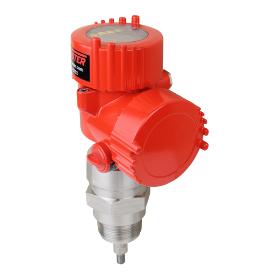
Summary of Contents for BINMASTER GWR-3000
- Page 1 Operating Instructions TDR sensor for continuous level and interface measurement of liquids GWR-3000 Modbus and Levelmaster protocol Converter version in second chamber Rod and cable probe Document ID: 41828...
-
Page 2: Table Of Contents
Set up with the quick setup ..................... 53 Saving the parameterisation data ................... 55 Diagnostics and servicing ....................56 Maintenance ........................56 Diagnosis memory ......................56 Status messages ......................57 Rectify faults ........................60 GWR-3000 • Modbus and Levelmaster protocol... - Page 3 10.8 Industrial property rights ....................96 10.9 Trademark ........................96 Safety instructions for Ex areas Take note of the Ex specific safety instructions for Ex applications. These instructions are attached as documents to each instrument with Ex approval and are part of the operating instructions. Editing status: 2020-01-24 GWR-3000 • Modbus and Levelmaster protocol...
-
Page 4: About This Document
The dot set in front indicates a list with no implied sequence. Sequence of actions Numbers set in front indicate successive steps in a procedure. Battery disposal This symbol indicates special information about the disposal of bat- teries and accumulators. GWR-3000 • Modbus and Levelmaster protocol... -
Page 5: For Your Safety
During work on and with the device, the required personal protective equipment must always be worn. Appropriate use GWR-3000 is a sensor for continuous level measurement. You can find detailed information about the area of application in chapter "Product description". Operational reliability is ensured only if the instrument is properly used according to the specifications in the operating instructions manual as well as possible supplementary instructions. -
Page 6: Eu Conformity
That is why we have introduced an environment management system with the goal of continuously improving company environmental pro- tection. The environment management system is certified according to DIN EN ISO 14001. Please help us fulfil this obligation by observing the environmental instructions in this manual: • Chapter "Packaging, transport and storage" • Chapter "Disposal" GWR-3000 • Modbus and Levelmaster protocol... -
Page 7: Product Description
The respective scope of delivery results from the order specification. Scope of this operating This operating instructions manual applies to the following instrument instructions versions: • Hardware from 1.0.0 • Software from 1.3.0 • Only for instrument versions without SIL qualification Type label The type label contains the most important data for identification and use of the instrument: GWR-3000 • Modbus and Levelmaster protocol... - Page 8 Download the VEGA Tools app from the "Apple App Store" or the "Google Play Store" • Scan the DataMatrix code on the type label of the instrument or • Enter the serial number manually in the app The instrument contains two different electronics in its housing cham- Electronics design bers: GWR-3000 • Modbus and Levelmaster protocol...
-
Page 9: Principle Of Operation
Functional principle - in- High frequency microwave impulses are guided along a steel cable or terface measurement rod. Upon reaching the product surface, a part of the microwave im- pulses is reflected. The other part passes through the upper product and is reflected by the interface. The running times to the two product layers are processed by the instrument. GWR-3000 • Modbus and Levelmaster protocol... - Page 10 Example: upper medium dielectric constant 2, lower medium at least dielectric constant 12. Gas phase (L3) • Air or gas mixture • Gas phase - dependent on the application, gas phase does not always exist (d2 = 0) GWR-3000 • Modbus and Levelmaster protocol...
-
Page 11: Packaging, Transport And Storage
The integrated Bluetooth module (optional) enables wireless adjust- ment via standard adjustment devices. VEGACONNECT The interface adapter VEGACONNECT enables the connection of communication-capable instruments to the USB interface of a PC. GWR-3000 • Modbus and Levelmaster protocol... - Page 12 The length and the process fittings can be configured individually. No different connection versions available. You can find further information in the operating instructions manual "Bypass tube VEGAPASS 81". Centering If you mount the GWR-3500 in a bypass tube or standpipe, you have to avoid contact to the bypass tube by using a spacer at the probe end. GWR-3000 • Modbus and Levelmaster protocol...
- Page 13 Cables with a diameter up to 8 mm (0.315 in) can thus be strained. For this purpose there is an internal thread (M12 or M8) in the gravity weight. GWR-3000 • Modbus and Levelmaster protocol...
-
Page 14: Mounting
Prior to setup you have to replace these protective caps with ap- proved cable glands or close the openings with suitable blind plugs. Note: Process conditions For safety reasons, the instrument must only be operated within the permissible process conditions. You can find detailed information on GWR-3000 • Modbus and Levelmaster protocol... -
Page 15: Mounting Instructions
Fig. 5: Vessel with conical bottom Type of vessel Plastic vessel/Glass vessel The guided microwave principle requires a metallic surface on the process fitting. Therefore, in plastic vessels, etc., use an instru- ment version with flange (from DN 50) or place a metal sheet (ø > 200 mm/8 in) beneath the process fitting when screwing it in. Make sure that the plate has direct contact with the process fitting. When mounting rod or cable probes in vessels without metal walls, e.g. in plastic vessels, the measured value can be influenced by GWR-3000 • Modbus and Levelmaster protocol... - Page 16 In such cases, always carry out a false signal suppression after mounting. You can find further information under "Setup procedure". DN25 ... DN150 ≤ 150 mm (5.91") > DN150 ... DN200 ≤ 100 mm (3.94") Fig. 7: Mounting socket When welding the socket, make sure that the socket is flush with the vessel top. GWR-3000 • Modbus and Levelmaster protocol...
- Page 17 "Technical data". Keep in mind for the adjustment that the default setting for the measuring range refers to water. GWR-3000 • Modbus and Levelmaster protocol...
- Page 18 In the case of cable probes, the cable can be strained. Keep in mind that the lower dead zone underneath the spacer in- creases if spacers are used. Buildup can form on the spacers. Strong buildup can influence the measurement. GWR-3000 • Modbus and Levelmaster protocol...
- Page 19 It does not matter if the standpipe is perforated or slotted for better mixing. Measuring probes can be mounted in standpipes up to DN 200. GWR-3000 • Modbus and Levelmaster protocol...
- Page 20 With rod probes, a spacer is generally not required. However, if there is a risk of the rod probe being pressed against the tube wall by in- flowing medium, you should mount a spacer at the probe end to avoid contact with the tube wall. In the case of cable probes, the cable can be strained. GWR-3000 • Modbus and Levelmaster protocol...
- Page 21 If there is a risk of the cable probe touching the vessel wall during operation due to product movements or agitators, etc., the measuring probe can be strained. For this purpose there is an internal thread (M12 or M8) in the gravity weight. GWR-3000 • Modbus and Levelmaster protocol...
- Page 22 Rod extension In case of difficult installation conditions, for example in a socket, the probe can be suitably adapted with a rod extension. To compensate for the resulting changes in signal runtime, let the instrument determine the probe length automatically. You can find further information in the supplementary instructions of the rod and cable components. GWR-3000 • Modbus and Levelmaster protocol...
-
Page 23: Connecting To Power Supply And Bus System
In the case of instrument housings with self-sealing NPT threads, it is not possible to have the cable entries screwed in at the factory. The free openings for the cable glands are therefore covered with red dust protection caps as transport protection. GWR-3000 • Modbus and Levelmaster protocol... -
Page 24: Connecting
3. Remove approx. 10 cm (4 in) of the cable mantle (signal output), strip approx. 1 cm (0.4 in) insulation from the ends of the indi- vidual wires 4. Insert the cable into the sensor through the cable entry GWR-3000 • Modbus and Levelmaster protocol... - Page 25 The terminal blocks are pluggable and can be removed from the housing insert. To do this, lift the terminal block with a small screwdriv- er and pull it out. When inserting the terminal block again, you should hear it snap in. GWR-3000 • Modbus and Levelmaster protocol...
-
Page 26: Wiring Plan
Internal connection to the connection compartment For display and adjustment module or interface adapter Connection compartment MODBUS power supply off on Fig. 17: Connection compartment USB interface 2 Slide switch for integrated termination resistor (120 Ω) Modbus signal Voltage supply Terminal Function Polarity Voltage supply GWR-3000 • Modbus and Levelmaster protocol... -
Page 27: Double Chamber Housing With Vegadis-Adapter
Fig. 19: View to the plug connector M12 x 1 Pin 1 Pin 2 Pin 3 Pin 4 Contact pin Colour, connection ca- Terminal, electronics ble in the sensor module Pin 1 Brown Pin 2 White Pin 3 Blue Pin 4 Black GWR-3000 • Modbus and Levelmaster protocol... -
Page 28: Switch-On Phase
PC • Status byte goes to fault value Then the actual measured value is output to the signal cable. The value takes into account settings that have already been carried out, e.g. default setting. GWR-3000 • Modbus and Levelmaster protocol... -
Page 29: Set Up The Sensor With The Display And Adjustment Module
The display and adjustment module is powered by the sensor, an ad- ditional connection is not necessary. Fig. 20: Insertion of the display and adjustment module Note: If you intend to retrofit the instrument with a display and adjustment module for continuous measured value indication, a higher lid with an inspection glass is required. GWR-3000 • Modbus and Levelmaster protocol... -
Page 30: Adjustment System
The output signal transmits a fault signal during the switch-on phase. The following information is displayed on the display and adjustment module during the startup procedure: • Instrument type GWR-3000 • Modbus and Levelmaster protocol... -
Page 31: Parameter Adjustment - Quick Setup
Max. adjustment • Min. adjustment • False signal suppression You can find the description of the individual menu items in the follow- ing chapter "Parameter adjustment - Extended adjustment". Parameter adjustment - Extended adjustment For technically demanding measuring points, you can carry out extended settings in "Extended adjustment". Main menu The main menu is divided into five sections with the following func- tions: GWR-3000 • Modbus and Levelmaster protocol... - Page 32 Capital letters from A … Z • Numbers from 0 … 9 • Special characters + - / _ blanks Units In this menu item you select the distance unit and the temperature unit. GWR-3000 • Modbus and Levelmaster protocol...
- Page 33 Application - Medium, In this menu item, you can define the type of medium (product). dielectric constant This menu item is only available if you have selected level measure- ment under the menu item "Application". You can choose between the following medium types: GWR-3000 • Modbus and Levelmaster protocol...
- Page 34 Adjust the requested percentage value with [+] and store with [OK]. Enter the appropriate distance value in m (corresponding to the percentage value) for the full vessel. The distance refers to the sensor GWR-3000 • Modbus and Levelmaster protocol...
- Page 35 Enter the respective distance value in m for the surface of the upper medium corresponding to the percentage value. Min. adjustment interface This menu item is only available if you have selected interface meas- urement under the menu item "Application". GWR-3000 • Modbus and Levelmaster protocol...
- Page 36 In the following, you have to enter the values for your vessel, for example the vessel height and the socket correction. For non-linear vessel forms, enter the vessel height and the socket correction. GWR-3000 • Modbus and Levelmaster protocol...
- Page 37 In the menu item "Current output Min./Max.", you determine the reac- tion of the current output during operation. The default setting is min. current 3.8 mA and max. current 20.5 mA. False signal suppression The following circumstances cause interfering reflections and can influence the measurement: • High mounting sockets GWR-3000 • Modbus and Levelmaster protocol...
- Page 38 This is useful if the saved false signal suppression no longer matches the metrological conditions in the vessel. Lock/Unlock adjustment In the menu item "Lock/unlock adjustment", you can protect the sen- sor parameters against unauthorized or inadvertent modification. The PIN is activated/deactivated permanently. GWR-3000 • Modbus and Levelmaster protocol...
- Page 39 The submenu points are described below. Menu language This menu item enables the setting of the requested national lan- guage. In delivery status, the sensor is set to English. Displayed value 1 In this menu item, you define the indication of the measured value on the display. You can display two different measured values. In this menu item, you define measured value 1. GWR-3000 • Modbus and Levelmaster protocol...
- Page 40 In delivery status, the lighting is switched on. 6.5.3 Diagnostics Sensor status In this menu item, the device status is displayed. When the instrument displays a failure message, you can here get detailed information on the failure reason. GWR-3000 • Modbus and Levelmaster protocol...
- Page 41 The respective min. and max. measured values are saved in the sensor. The values are displayed in the menu item "Peak values Ad- ditional". This menu item displays the peak values of the electronics tempera- ture as well as the dielectric constant. GWR-3000 • Modbus and Levelmaster protocol...
- Page 42 During simulation, the simulated value is output as 4 … 20 mA current value and digital HART signal. Push the [ESC] key to deactivate the simulation. Information: The simulation is terminated automatically 60 minutes after the activa- tion of the simulation. GWR-3000 • Modbus and Levelmaster protocol...
- Page 43 Basic settings: Restores the parameter settings, incl. special param- eters, to the default values of the respective instrument. Any stored false signal suppression or user-programmed linearisation curve, as well as the measured value memory, are deleted. GWR-3000 • Modbus and Levelmaster protocol...
- Page 44 Scaling level - 0 % corresponds to Scaling variable - Interface Volume Scaling unit - Interface Litres Scaling format - Interface Without decimal positions Scaling interface - 100 % corresponds to Scaling interface - 0 % corresponds to GWR-3000 • Modbus and Levelmaster protocol...
- Page 45 The following data or settings for adjustment of the display and ad- justment module are saved: • All data of the menu "Setup" and "Display" • In the menu "Additional adjustments" the items "Reset, Date/Time" • Special parameters GWR-3000 • Modbus and Levelmaster protocol...
- Page 46 Scaling level - Scaling format In menu item "Scaling format" you define the scaling format on the display and the scaling of the measured level value for 0 % and 100 %. GWR-3000 • Modbus and Levelmaster protocol...
- Page 47 In menu item "Current output, variable" you specify which measured output size variable the current output refers to. In menu item "Current output, adjustment" you can assign a respec- Current output - Current output adjustment tive measured value to the current output. GWR-3000 • Modbus and Levelmaster protocol...
- Page 48 6.5.5 Info Device name In this menu, you read out the instrument name and the instrument serial number. Instrument version In this menu item, the hardware and software version of the sensor is displayed. GWR-3000 • Modbus and Levelmaster protocol...
-
Page 49: Saving The Parameterisation Data
In the display and adjust- If the instrument is equipped with a display and adjustment module, ment module the parameter adjustment data can be saved therein. The procedure is described in menu item "Copy device settings". GWR-3000 • Modbus and Levelmaster protocol... -
Page 50: Setting Up Sensor And Modbus Interface With Pactware
• Sensor electronics • Modbus electronics Fig. 24: Connecting the PC via USB to the Modbus electronics 1 USB cable to the PC To the RS 485 cable Connection of the PC to the RS 485 cable is carried out via a stand- ard interface adapter RS 485/USB. GWR-3000 • Modbus and Levelmaster protocol... -
Page 51: Parameter Adjustment With Pactware
Further setup steps are described in the operating instructions manu- al "DTM Collection/PACTware" attached to each DTM Collection and which can also be downloaded from the Internet. Detailed descrip- tions are available in the online help of PACTware and the DTMs. GWR-3000 • Modbus and Levelmaster protocol... -
Page 52: Set Instrument Address
"Software". The full version is avail- able on CD from the agency serving you. Set instrument address The GWR-3000 requires an address for participating as a Slave in the Modbus communication. The addess setting is carried out via a PC with PACTware/DTM or Modbus RTU. -
Page 53: Set Up With The Quick Setup
The quick setup is another option for parameter adjustment of the sensor. It allows fast, convenient adjustment of the most important parameters to adapt the sensor quickly to standard applications. To use it, select the function "Quick setup" in the start screen. GWR-3000 • Modbus and Levelmaster protocol... - Page 54 2 Extended adjustment Maintenance Quick setup With quick setup you can carry out the parameter adjustment of GWR-3000 for your application in just a few simple steps. The assistant-driven adjustment includes the basic settings for simple, reliable setup and commissioning. Information: If the function is inactive, then possibly no instrument is connected.
-
Page 55: Saving The Parameterisation Data
7 Setting up sensor and Modbus interface with PACTware Saving the parameterisation data We recommend documenting or saving the parameterisation data via PACTware. That way the data are available for multiple use or service purposes. GWR-3000 • Modbus and Levelmaster protocol... -
Page 56: Diagnostics And Servicing
• Modification of a parameter • Switch-on and switch-off times • Status messages (according to NE 107) • Error messages (according to NE 107) The data are read out via a PC with PACTware/DTM or the control system with EDD. GWR-3000 • Modbus and Levelmaster protocol... -
Page 57: Status Messages
This status message is always active. It cannot be deactivated by the user. Function check: The instrument is being worked on, the measured value is temporarily invalid (for example during simulation). This status message is inactive by default. GWR-3000 • Modbus and Levelmaster protocol... - Page 58 Disconnect operating voltage briefly munication Communication Send instrument for repair error F125 Temperature of the electronics in the Check ambient temperature Bit 7 non-specified range Impermissible Insulate electronics electronics tem- Use instrument with higher temper- perature ature range GWR-3000 • Modbus and Levelmaster protocol...
- Page 59 Level echo in the close range not Reduce level Bit 9 of available Byte 14 … 24 Overfilling 100 % adjustment: Increase value Check mounting socket Remove possible interfering signals in the close range Use coaxial probe GWR-3000 • Modbus and Levelmaster protocol...
-
Page 60: Rectify Faults
The operator of the system is responsible for taking suitable meas- tion occurs ures to rectify faults. The first measures are: Fault rectification • Evaluation of fault messages • Checking the output signal • Treatment of measurement errors GWR-3000 • Modbus and Levelmaster protocol... - Page 61 If the output level is constant, the cause could also be the fault setting of the current output to "Hold value". If the level is too low, the reason could be a line resistance that is too high GWR-3000 • Modbus and Levelmaster protocol...
- Page 62 Eliminate false signals in the close range ≥ 100 % or 0 m distance close range due to false signals in the Check installation conditions close range. The sensor goes into over- If possible, switch off the function "Over- fill protection mode. The max. level (0 m fill protection" distance) as well as the status message "Overfill protection" are output. time GWR-3000 • Modbus and Levelmaster protocol...
-
Page 63: Exchanging The Electronics Module
In both cases, the serial number of the sensor is needed. The serial numbers are stated on the type label of the instrument, on the inside of the housing as well as on the delivery note. When loading on site, the order data must first be downloaded from the Internet (see operating instructions "Electronics module"). GWR-3000 • Modbus and Levelmaster protocol... -
Page 64: Exchanging The Cable/Rod
6. Exert counterforce with the second fork spanner and tighten the rod or cable on the flat surfaces with the following torque. Rod ø 8, cable ø 2 and 4: 6 Nm (4.43 lbf ft) Rod ø 12: 10 Nm (7.37 lbf ft) Fig. 30: Exchange cable or rod Information: Please maintain the specified torque so that the max. tensile strength of the connection remains. GWR-3000 • Modbus and Levelmaster protocol... -
Page 65: Software Update
C Centering weight - cable ø 2 mm Threaded pins Thread M8 for eye-bolt Fixing screw - centering weight Software update The device software can be updated in the following ways: • Interface adapter VEGACONNECT • HART signal • Bluetooth GWR-3000 • Modbus and Levelmaster protocol... -
Page 66: How To Proceed If A Repair Is Necessary
Clean the instrument and pack it damage-proof • Attach the completed form and, if need be, also a safety data sheet outside on the packaging • Ask the agency serving you to get the address for the return ship- ment. You can find the agency on our homepage. GWR-3000 • Modbus and Levelmaster protocol... -
Page 67: Dismount
Pass the instrument directly on to a specialised recycling company and do not use the municipal collecting points. If you have no way to dispose of the old instrument properly, please contact us concerning return and disposal. GWR-3000 • Modbus and Levelmaster protocol... -
Page 68: Supplement
Ʋ Seal between housing and housing lid Silicone SI 850 R Ʋ Inspection window in housing cover Plastic housing: Polycarbonate (optional) Metal housing: Glass Ʋ Ground terminal 316L Ʋ Cable gland PA, stainless steel, brass Ʋ Sealing, cable gland Ʋ Blind plug, cable gland GWR-3000 • Modbus and Levelmaster protocol... - Page 69 ±(2 mm + 0.05 % of the cable length) Lateral load Ʋ Rod: ø 8 mm (0.315 in) 10 Nm (7.38 lbf ft) Ʋ Rod: ø 12 mm (0.472 in) 30 Nm (22.13 lbf ft) GWR-3000 • Modbus and Levelmaster protocol...
- Page 70 45 … 75 % Ʋ Air pressure +860 … +1060 mbar/+86 … +106 kPa (+12.5 … +15.4 psig) Mounting, reference conditions Ʋ Min. distance to internal installations > 500 mm (19.69 in) Ʋ Vessel metallic, ø 1 m (3.281 ft), centric mounting, process fit- ting flush with the vessel ceiling GWR-3000 • Modbus and Levelmaster protocol...
- Page 71 Typical deviation - Interface measure- ± 5 mm (0.197 in) ment Typical deviation - Total level interface See following diagrams measurement Typical deviation - Level measurement See following diagrams 2)3) With interface measurement = 2.0. Depending on the mounting conditions, deviations can occur which can be rectified by adapting the adjustment or changing the measured value offset in the DTM service mode. The dead zones can be optimized via a false signal suppression. GWR-3000 • Modbus and Levelmaster protocol...
- Page 72 -2 mm (-0.079 ") -10 mm (-0.591 ") 0,15 m 0,3 m 0,07 m (5.906 (11.811 " ") (2.756 ") 0,05 m (1.97 ") Fig. 34: Deviation GWR-3000 in rod version in oil Dead zone (no measurement possible in this area) Probe length GWR-3000 • Modbus and Levelmaster protocol...
- Page 73 (3.15 ") Fig. 36: Deviation GWR-3000 in cable version (ø 2 mm/0.079 in), in medium oil Dead zone (no measurement possible in this area) When using a centering weight, it is only possible to measure up to the upper edge of the cerntering weight. Probe length GWR-3000 • Modbus and Levelmaster protocol...
- Page 74 2 mm (0.079 ") -2 mm (-0.079 ") -15 mm (-0.591 ") 0,1 m 0,2 m 0,07 m (3.937 (7.874 " " (2.756 ") Fig. 38: Deviation GWR-3000 in cable version (ø 4 mm/0.157 in, PFA-coated) in water Dead zone (no measurement possible in this area) Probe length GWR-3000 • Modbus and Levelmaster protocol...
- Page 75 0.08 % 0.52 % Hydrogen 20 °C (68 °F) -0.01 % 0.1 % 0.61 % 200 °C (392 °F) -0.02 % 0.05 % 0.37 % 400 °C (752 °F) -0.02 % 0.03 % 0.25 % GWR-3000 • Modbus and Levelmaster protocol...
- Page 76 -20 … +150 °C (-4 … +302 °F) Ʋ FFKM (Kalrez 6375) - with tempera- -20 … +200 °C (-4 … +392 °F) ture adapter Time span after a sudden measuring distance change by max. 0.5 m in liquid applications, max 2 m with bulk solids applications, until the output signal has taken for the first time 90 % of the final value (IEC 61298-2). GWR-3000 • Modbus and Levelmaster protocol...
- Page 77 -40°C / -40°F Fig. 41: Ambient temperature - process temperature, version with temperature adapter Ambient temperature Process temperature (depending on the seal material) Aluminium housing Plastic housing Stainless steel housing, precision casting Stainless steel housing, electropolished GWR-3000 • Modbus and Levelmaster protocol...
- Page 78 Output of the temperature values Ʋ Indication Via the display and adjustment module Ʋ Output Via the respective output signal Voltage supply Operating voltage 8 … 30 V DC Power consumption max. 520 mW Reverse voltage protection Integrated GWR-3000 • Modbus and Levelmaster protocol...
-
Page 79: Basics Modbus
1200 m. The bus must be terminated on both sides at the last bus participant with a terminating resistor of 120 Ohm. The resistor is already integrated in the GWR-3000 and is activated/deactivated via a slide switch. Galvanic separation between electronics and metal housing parts When used with fulfilled housing protection GWR-3000 •... - Page 80 Fig. 42: Bus architecture Modbus Connection resistor Bus participant Voltage supply Protocol description The GWR-3000 is suitable for connection to the following RTUs with Modbus RTU or ASCII protocol. Protocol ABB Totalflow Modbus RTU, ASCII Bristol ControlWaveMicro Modbus RTU, ASCII...
-
Page 81: Modbus Register
(4 bytes) according to IEEE 754 are transmitted with individually selectable order of the data bytes (byte transmission order). This "Byte transmission order" is determined in the parameter "Format Code". Hence the RTU knows the registers of the GWR-3000 which must be contacted for the variables and status information. - Page 82 Primary Variable in Byte Order BACD (Middle Endian) 2204 DWord Secondary Variable in Byte Order BACD (Middle Endian) 2206 DWord Third Variable in Byte Order BACD (Middle Endian) 2208 DWord Quarternary Variable in Byte Order BACD (Middle Endian) GWR-3000 • Modbus and Levelmaster protocol...
-
Page 83: Modbus Rtu Commands
Parameter Length Code/Data Request: Function Code 1 Byte 0x04 Start Address 2 Bytes 0x0000 to 0xFFFF Number of Registers N*2 Bytes 1 to 127 (0x7D) GWR-3000 • Modbus and Levelmaster protocol... - Page 84 With this function code, several holding registers can be writen. Only registers can be written in an enquiry which are immediately consecutive. If there are gaps (registers do not exist) between the registers, then they cannot be written in a telegram. GWR-3000 • Modbus and Levelmaster protocol...
- Page 85 Next Object ID 1 Byte Object ID number Number of Objects 1 Byte List of Object ID 1 Byte List of Object length 1 Byte List of Object value 1 Byte Depending on the Object ID GWR-3000 • Modbus and Levelmaster protocol...
-
Page 86: Levelmaster Commands
10 Supplement 10.5 Levelmaster commands The GWR-3000 is also suitable for connection to the following RTUs with Levelmaster protocol. The Levelmaster protocol is often called "Siemens" "Tank protocol". Protocol ABB Totalflow Levelmaster Kimray DACC 2000/3000 Levelmaster Thermo Electron Autopilot Levelmaster Parameters for the bus communication... - Page 87 = 81, even = 71 (default), odd = 71 Response: Set Baud Rate 11 characters ASCII Example: U01B9600E71 Change instrument on address 1 to baudrate 9600, parity even, 7 data bits, 1 stop bit GWR-3000 • Modbus and Levelmaster protocol...
- Page 88 = milliseconds (50 up to 250), default = 127 ms Error codes Error Code Name EE-Error Error While Storing Data in EEPROM FR-Error Erorr in Frame (too short, too long, wrong data) LV-Error Value out of limits GWR-3000 • Modbus and Levelmaster protocol...
-
Page 89: Configuration Of Typical Modbus Hosts
10 Supplement 10.6 Configuration of typical Modbus hosts Fisher ROC 809 (Rx/Tx -) (Rx/Tx +) +30 Vdc Fig. 43: Connection of GWR-3000 to RTU Fisher ROC 809 GWR-3000 RTU Fisher ROC 809 Voltage supply ABB Total Flow Bus + Bus - VBAT Fig. 44: Connection of GWR-3000 to RTU ABB Total Flow GWR-3000 RTU ABB Total Flow GWR-3000 • Modbus and Levelmaster protocol... - Page 90 Voltage supply Bristol ControlWave Micro RS 485 on COM1 1 +SV 2 RX- 3 TX- 4 GND 5 RXT 6 TXT 7 not used 8 not used +30 Vdc Fig. 46: Connection of GWR-3000 to RTU Bristol ControlWave Micro GWR-3000 RTU Bristol ControlWave Micro Voltage supply GWR-3000 • Modbus and Levelmaster protocol...
-
Page 91: Dimensions
• ScadaPack - Register address for 1302 is address 31303 10.7 Dimensions The following dimensional drawings represent only an extract of all possible versions. Detailed dimensional drawings can be downloaded at www.vega.com/downloads under "Drawings". GWR-3000 • Modbus and Levelmaster protocol... - Page 92 10 Supplement Housing ~ 87 mm ~ 84 mm (3.43") ø 84 mm (3.31") ø 79 mm (3.31") (3.11") M16x1,5 M16x1,5 M20x1,5/ M20x1,5/ ½ NPT ½ NPT Fig. 48: Dimensions housing (with integrated display and adjustment module the housing is 9 mm/0.35 in higher) Plastic double chamber Aluminium/Stainless steel double chamber GWR-3000 • Modbus and Levelmaster protocol...
- Page 93 10 Supplement GWR-3000, cable version with gravity weight SW 36 (1.42") (G¾, ¾ NPT) SW 41 (1.61") (G1, 1 NPT) SW 46 (1.81") (G1½, 1½ NPT) G¾, ¾ NPT, G1, 1 NPT, G1½, 1½ NPT ø 4 mm (0.16") ø 4 mm (0.16")
- Page 94 10 Supplement GWR-3000, cable version with centering weight SW 36 (1.42") (G¾, ¾ NPT) SW 41 (1.61") (G1, 1 NPT) SW 46 (1.81") (G1½, 1½ NPT) G¾, ¾ NPT, G1, 1 NPT, G1½, 1½ NPT ø 4 mm (0.16") ø 4 mm (0.16")
- Page 95 G1½, 1½ NPT G1½, 1½ NPT ø 8 mm ø 12¨mm (0.32") (0.47") Fig. 51: GWR-3000, threaded version Sensor length, see chapter "Technical data" Rod version ø 8 mm (0.315 in) Rod version ø 12 mm (0.472 in) GWR-3000 • Modbus and Levelmaster protocol...
-
Page 96: Industrial Property Rights
Линии продукции фирмы ВЕГА защищаются по всему миру правами на интеллектуальную собственность. Дальнейшую информацию смотрите на сайте www.vega.com. VEGA系列产品在全球享有知识产权保护。 进一步信息请参见网站<www.vega.com。 10.9 Trademark All the brands as well as trade and company names used are property of their lawful proprietor/ originator. GWR-3000 • Modbus and Levelmaster protocol... - Page 97 Factory calibration date 49 – Display and adjustment module with False signal suppression 37 heating 12 Fault – Fixing facility 13 – Rectification 60 – Rod components 12 Fault rectification 60 – Spacer 12 Functional principle 9 Reset 43 GWR-3000 • Modbus and Levelmaster protocol...
- Page 98 INDEX Scaling measured value 46, 47 Sensor characteristics 49 Sensor status 40 Service hotline 63 Simulation 42 Special parameters 48 Type label 7 Type of medium 33 Units 32 GWR-3000 • Modbus and Levelmaster protocol...
- Page 99 Notes GWR-3000 • Modbus and Levelmaster protocol...
- Page 100 Subject to change without prior notice © VEGA Grieshaber KG, Schiltach/Germany 2020 BinMaster Phone: 402-434-9102 Fax: 402-434-9133 7201 N 98th St Lincoln, NE 68507 E-mail: info@binmaster.com www.binmaster.com 925-0388 Rev A...
Need help?
Do you have a question about the GWR-3000 and is the answer not in the manual?
Questions and answers