Table of Contents
Advertisement
Quick Links
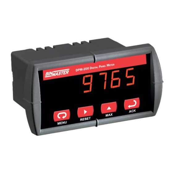
DPM-200 Digital Panel Meter
Instruction Manual
1/8 DIN Digital Panel Meter with NEMA 4X, IP65 Front
•
4-20 mA, ± 10 V, TC & RTD Field Selectable Inputs
•
•
Easy Field Scaling in Engineering Units without Applying an Input
Full 4-Digit Display, 0.56" (14.2 mm) or 1.20" (30.5 mm)
•
•
Shallow Depth Case Extends Only 3.6" (91 mm) Behind Panel
Isolated 24 VDC @ 200 mA Transmitter Power Supply Option
•
•
2 Relays + Isolated 4-20 mA Output Options
Free PC-Based MeterView Programming & Monitoring Software
•
•
No Assembly Required
Sunlight Readable Display
•
Operating Temperature Range: -40 to 65°C (-40 to 149°F)
•
•
UL & C-UL Listed. E160849; UL 508 Industrial Control Equipment
Input Power Options: 85-265 VAC / 90-265 VDC or 12-36 VDC / 12-24 VAC
•
•
Duplex Pump Controller with Alternation Capability
External Contacts for Remote Button Operation (DPM-200 X2 Only)
•
•
USB, RS-232, & RS-485 Serial Communication Adapters Options
Modbus RTU Communication Protocol Standard
•
•
Copy Meter Settings to Other DPM-200 Meters
Password Protection
•
Max/Min Display
•
•
High & Low Alarms with Multiple Reset Actions
3-Year Warranty
•
BINMASTER
Division of Garner Industries
7201 North 98th Street, Lincoln, NE 68507 USA
•
Tel (800) 278-4241
Fax: (402) 434-9133
www.binmaster.com
Advertisement
Table of Contents
Troubleshooting

Subscribe to Our Youtube Channel
Related Manuals for BINMASTER DPM-200


Summary of Contents for BINMASTER DPM-200
- Page 1 Input Power Options: 85-265 VAC / 90-265 VDC or 12-36 VDC / 12-24 VAC • • Duplex Pump Controller with Alternation Capability External Contacts for Remote Button Operation (DPM-200 X2 Only) • • USB, RS-232, & RS-485 Serial Communication Adapters Options Modbus RTU Communication Protocol Standard •...
- Page 2 Read complete instructions prior to installation and operation of the meter. Risk of electric shock or personal injury. • Note: The DPM-200 is not powered from USB connection and requires external power to be programmed. This product is not recommended for life support •...
-
Page 3: Table Of Contents
DPM-200 Digital Panel Meter Instruction Manual Table of Contents Introduction ......................6 Ordering Information ..................6 Specifications ..................... 7 General ......................7 Process Input ....................7 Temperature Inputs ..................7 Relays Option ....................8 Serial Communications .................. 8 Isolated 4-20 mA Transmitter Output ............8 External Button Contacts (X2 Models Only) .......... - Page 4 DPM-200 Digital Panel Meter Instruction Manual Select Menu (SElc) ..................30 Linear or Square Root Function (linr or Sqrt) .......... 30 Low-Flow Cutoff (cutF) ................30 Display Intensity (inty) ................31 Meter Copy Function (Copy) ................ 31 Meterview Software ..................32 Remote Programming ..................
- Page 5 Figure 34. 4-20 mA Output Powered by Meter ........... 16 Figure 35. 4-20 mA Output Powered Externally ..........16 Figure 36. DPM-200 X2 Powers Both the Heater and 4-20 mA Input Signal ..16 Figure 38. Meter Copy Connection ..............31...
-
Page 6: Introduction
There are two power X2 can be read easily from distances of up to 30 feet! options for the DPM-200: 85 to 265 VAC or 12-36 VDC The intensity of the display on both versions of the... -
Page 7: Specifications
(-10 option) P1 & P2: 24 VDC ±10% @ 200 mA & 40 mA max DPM-200: 0.56" (14.2 mm); Display DPM-200 X2: 1.20" (30.5 mm) red (-20 option) LED, 4 digits (-1999 to 9999) Accuracy ±0.05% FS ±1 count;... -
Page 8: Relays Option
DPM-200 Digital Panel Meter Instruction Manual Relays Option Serial Communications 2 Form C (SPDT); rated 3 A @ 30 VDC Rating Protocol Modbus RTU or 3 A @ 250 VAC resistive load; Meter PDC protocol: 0 - 99 1/14 HP (≈ 50 watts) @ 125/250 VAC... -
Page 9: Compliance Information
DPM-200 Digital Panel Meter Instruction Manual Compliance Information Safety Ul Listed USA and Canada UL 508 Industrial Control Equipment Ul File Number E160849 Front Panel UL Type 4X, NEMA 4X, IP65; panel gasket provided Low Voltage EN 61010-1:2010 Directive Safety requirements for measurement,... -
Page 10: Safety Information
DPM-200 Digital Panel Meter Instruction Manual Safety Information Mounting Dimensions Read complete instructions prior to installation • 1.76" (45mm) and operation of the meter. • Risk of electric shock. • Hazardous voltages exist within enclosure. • Installation and service should be performed only 2.45"... -
Page 11: Connections
It also identifies the location of the RTD/TC selector switch. The images below show all connector configurations for the DPM-200. Note that the connector in the upper left of the diagram has different configurations based on the model. -
Page 12: Figure 11. Connector Labeling For Pd765-7R5-00-Bm
DPM-200 Digital Panel Meter Instruction Manual Figure 11. Connector Labeling for PD765-7R5-00-BM Figure 15. Connector Labeling for PD765-#X2-00-BM Figure 12. Connector Labeling for PD765-6R5-10-BM Figure 16. Connector Labeling for PD765-6X2-10-BM Figure 13. Connector Labeling for PD765-#X0-00-BM Figure 17. Connector Labeling for PD765-#X3-00-BM Figure 14. -
Page 13: Power Connections
DPM-200 Digital Panel Meter Instruction Manual Signal Connections Signal connections are made to a five-terminal connector labeled SIGNAL shown in Figures 4-21. See page 11. Connector Labeling. The COM (common) terminal is the return for all types of input signals. -
Page 14: Figure 26. Thermocouple Input Connections
DPM-200 Digital Panel Meter Instruction Manual Thermocouple and RTD Connections The following figures show examples for thermocouple and RTD connections. The RTD/TC selector switch must be set to the proper position for the meter to accept the selected temperature input. -
Page 15: Relays And 24 V Output Connections
BinMaster to prevent disrupting the microprocessor’s operation. The snubbers also prolong the life of the relay contacts. RC networks are available from BinMaster and should Suppression can be obtained with resistor-capacitor be applied to each relay contact switching an (RC) networks assembled by the user or purchased as inductive load. -
Page 16: Ma Output & Input Signal Connections
For instance, for level transmitters that require SIGNAL CONNECTOR mA OUT 24V OUT the use of a heated lens, the DPM-200’s 200 mA power supply could be used to power both the heated lens and the 4-20 mA signal from the transmitter. RELAY2... -
Page 17: Setup And Programming
Front Panel Buttons and Status LED Indicators This section describes how to program the DPM-200 using the front panel buttons. The DPM-200 can also DPM-200 Standard Display be programmed using Meterview Software as de- scribed on page 32, or by copying the programing from meter to the next as described on page 31. -
Page 18: Display Functions And Messages
DPM-200 Digital Panel Meter Instruction Manual Display Functions and Messages Display Parameter Action/Setting Program set point 1 Set1 Set 1 The meter displays various functions and messages Reset 1 Program reset point 1 rSt1 during setup/programming and operation. The Setup relay 2... -
Page 19: Main Menu
DPM-200 Digital Panel Meter Instruction Manual Main Menu Setting Up the Meter (setu) The main menu consists of the most commonly used The Setup menu is used to select: functions: Setup and Password. Input signal the meter will accept •... -
Page 20: Setting The Decimal Point (Dc. P T)
DPM-200 Digital Panel Meter Instruction Manual Programming the Meter (prog) If RTD is selected, the display shows A385 or A392. Select the coefficient to match the RTD sensor, either 0.00385 (A385, European curve) or 0.00392 (A392, The meter may either be scaled (ScAL) without American curve). -
Page 21: Calibrating The Meter (Cal)
DPM-200 Digital Panel Meter Instruction Manual Minimum Input Span Recommended Calibration Points The minimum input span is the minimum difference To recalibrate the meter, it is recommended to use between input 1 and input 2 signals required to the Fahrenheit scale; this will give a greater degree of complete the calibration or scaling of the meter. -
Page 22: Setting The Relay Operation (Rely)
DPM-200 Digital Panel Meter Instruction Manual Setting the Relay Operation (rely) Setting the Relay Action This menu allows you to set up the operation of the The relays’ Action menu allows the user to set up the relays: operation of the relays. The relays may be set up for... -
Page 23: Relay And Alarm Operation
DPM-200 Digital Panel Meter Instruction Manual Setting Fail-Safe Operation Sensor Break Operation The following graphs illustrate the operation of how The fail-safe operation is set independently for each the meter reacts when a sensor break is detected. relay. Select on to enable or select off to disable fail- safe operation. - Page 24 DPM-200 Digital Panel Meter Instruction Manual Low Alarm Operation (Set < Reset) Time Delay Operation The following graphs show the operation of the time delay function. If the signal crosses the set point, the On time delay timer starts and the relay trips when the time delay has elapsed.
- Page 25 DPM-200 Digital Panel Meter Instruction Manual High Alarm with Fail-Safe Operation Low Alarm with Fail-Safe Operation (Set > Reset) (Set < Reset) Fail-safe operation: relay coil is energized in non- Fail-safe operation: relay coil is energized in non- alarm condition. In case of power failure, relay will go alarm condition.
- Page 26 Pump Controller with Dual-Pump Alternation The DPM-200 can be used as a low-cost pump controller when combined with a continuous level transmitter. One of the most common pump control application is shown below: controlling and alternating two pumps. The goal is to control the level between 1000 and 6000 gallons.
-
Page 27: Scaling The 4-20 Ma Analog Output (Aout)
DPM-200 Digital Panel Meter Instruction Manual Scaling the 4-20 mA Analog Output Program the Sensor Break Output (Aout) Value (SEbr) The 4-20 mA analog output can be scaled to provide The sensor break value corresponds to the output signal generated when the meter detects a sensor a 4-20 mA signal for any display range selected. -
Page 28: Setting Up The Password (Pass)
DPM-200 Digital Panel Meter Instruction Manual Setting Up the Password (pass) Forgot the Password? The password may be disabled by the following The Password menu is used to program a four-digit procedure: password to prevent unauthorized changes to the Note display reading prior to pressing the Menu programmed parameter settings. -
Page 29: Offset Adjustment (Adj)
DPM-200 Digital Panel Meter Instruction Manual Offset Adjustment (Adj) Display Functions and Messages This parameter allows the user to select an offset Display Parameter Action/Setting adjustment to the temperature being displayed. Offset another meter adjustment values can be either positive or negative... -
Page 30: Serial Communications (Serl)
00 to 99 for PDC protocol and from 1 to 247 for Modbus protocol. The transmit delay may be set between 0 and 199 ms. The DPM-200 can also be connected directly to Low-Flow Cutoff (cutF) another DPM-200 through an optional cable The low-flow cutoff feature allows the meter to be assembly. -
Page 31: Display Intensity (Inty)
DPM-200 Digital Panel Meter Instruction Manual Display Intensity (inty) Meter Cloning Instructions The Display Intensity function allows the selection of eight levels of intensity for various lighting conditions. • Do not connect the two meters to the same 4-20 mA loop while cloning. Internal calibration may be affected. -
Page 32: Meterview Software
MeterView Installation 1. Download software from the included CD 2. Read instructions & copy serial # of desired Note: DPM-200 meter is not powered from USB connection MeterView version and requires external power to be programmed. 3. Download Installation file to computer The easiest and quickest way to program your DPM- 4. -
Page 33: Meterview Main Window
DPM-200 Digital Panel Meter Instruction Manual MeterView Main Window Main Window Menus The MeterView main window contains the following The main MeterView window shows the present menus: reading(s), relays/alarm status, tag number(s) • File menu and selected engineering units, along with other •... -
Page 34: Configuration Window
DPM-200 Digital Panel Meter Instruction Manual Configuration Window Right Click Menu By right clicking on a meter on the screen a menu will Click on Configure in the right click menu to open a appear with the following options: meter’s configuration window. The following settings... -
Page 35: Password Menu
DPM-200 Digital Panel Meter Instruction Manual Set Up Decimal Point Click on the arrow next to the dd.dd box and then It is recommended to save a configuration click on the desired decimal point position. Decimal file before changing any setting and before point selection is available for 4-20 mA and 0-10 V in- any calibration operation. -
Page 36: Scaling Tab
DPM-200 Digital Panel Meter Instruction Manual Scaling Tab Info Tab In the configuration window, click on the Scaling tab In the configuration window, click on the info tab to to view the scaling settings for process inputs (current view the firmware number and version. -
Page 37: Serial Communication Setup
DPM-200 Digital Panel Meter Instruction Manual Serial Communication Setup Logging Meter Data to File 1. Click on the arrow next to the Interval box to select an interval from 2 to 60 or select manual Addresses for the DPM-200 to log the data only when the Log button is... -
Page 38: Internal Calibration (Ical)
DPM-200 Digital Panel Meter Instruction Manual Internal Calibration (ICal) For instructions on how to program numeric values see Setting Numeric Values, page 19. There is no need to recalibrate the meter • when first received from the factory. The meter is factory calibrated prior to •... -
Page 39: Operation
DPM-200 Digital Panel Meter Instruction Manual Operation Maximum/Minimum Readings The main function of the front panel buttons during For process inputs, the meter is capable of accepting operation is to display the maximum and minimum positive and negative signals and displaying these readings reached by the process or temperature signals in engineering units from -1999 to 9999 (e.g. -
Page 40: Troubleshooting
DPM-200 Digital Panel Meter Instruction Manual Troubleshooting Reset Meter to Factory Defaults When the parameters have been changed in a way Due to the many features and functions of the DPM- that is difficult to determine what’s happening, it might 200, it’s possible that the setup of the meter does not... -
Page 41: Factory Defaults & User Settings
DPM-200 Digital Panel Meter Instruction Manual Factory Defaults & User Settings Parameter Display Default User Setting Setting The following table shows the factory setting for most of the programmable parameters on the meter. Next Break 1 Brk1 to the factory setting, the user may record the new... -
Page 42: Troubleshooting Tips
DPM-200 Digital Panel Meter Instruction Manual Troubleshooting Tips This meter is a highly sophisticated instrument with an extensive list of features and capabilities. If the front panel but- tons are used to program the meter, it may be a difficult task to keep everything straight. That is why we strongly rec- ommend the use of the MeterView software for all programming activities. -
Page 43: Quick Interface Reference Guide
DPM-200 Digital Panel Meter Instruction Manual Quick Interface Reference Guide Run Mode A385 4-20 mA Input Display A392 Max/Min 0-10 V Setup Type J Type K Password Type T Type T.0 Locked Unlocked Type E TC or RTD? Decimal dddd Point d . - Page 44 DPM-200 Digital Panel Meter Instruction Manual Pushbutton Function Menu Go to Programming Mode or leave Programming, Advanced Features, and Max/Min Modes. Right Arrow Move to next digit. Up Arrow Move to next selection or increment digit. Enter/Ack Accept selection/value and move to next selection.
-
Page 45: Eu Declaration Of Conformity
EU Declaration of Conformity Issued in accordance with ISO/IEC 17050-1:2004. Precision Digital Corporation 233 South Street Hopkinton, MA 01748 USA as the manufacturer, declare under our sole responsibility that the product(s), Model PD765 Trident Process and Temperature Meter to which this declaration relates, is in conformity with the European Union Directives shown below: 2014/35/EU Low Voltage Directive 2014/30/EU... - Page 46 DPM-200 Digital Panel Meter Instruction Manual Contact BinMaster Technical Support Call: (800) 278-4241 or (402) 434-9102 Fax: (402) 434-9133 Email: support@binmaster.com Sales Support Call: (800) 278-4241 or (402) 434-9102 Fax: (402) 434-9133 Email: info@binmaster.com Place Orders Email: info@binmaster.com For the latest version of this manual please visit www.binmaster.com...
Need help?
Do you have a question about the DPM-200 and is the answer not in the manual?
Questions and answers