Table of Contents

Subscribe to Our Youtube Channel
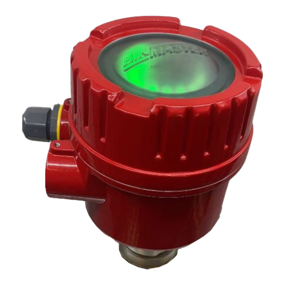
Summary of Contents for BINMASTER BMRX-300
- Page 1 BMRX-300 Rotary Level Indicator Operating Instructions Please Read Carefully BinMaster: Division of Garner Industries LLC 7201 N. 98th St. Lincoln, NE 68507 402-434-9102 info@binmaster.com | www.binmaster.com 925-0417 REV A 0124...
-
Page 2: Table Of Contents
TABLE OF CONTENTS GENERAL SPECIFICATIONS .................... 3 SAFETY SUMMARY ......................4 1.0 INTRODUCTION ......................5 2.0 INSTALLATION ......................5 2.1 Mounting Summary ..................5 2.2 Location and Mounting ................7 2.3 Input Power and Field Wiring ..............9 2.4 Grounding ....................10 3.0 DPDT RELAY ...................... -
Page 3: General Specifications
SPECIFICATIONS BMRX-200 DC GENERAL SPECIFICATIONS Power Supply: 12 to 24 VDC Supply Tolerance: -15% to +10% Load: AC Models 6 VA Fuse: 2 AMP 250V TR5 Time Lag PCB mount Ambient Temperature: (Electronics) -40° F to +158° F (-40° C to +70° C) Process Temperature: 400°... -
Page 4: Safety Summary
SAFETY SAFETY SUMMARY Review the safety precautions to avoid injury and prevent damage to equipment. The product should be installed, commissioned, and maintained by qualified, authorized personnel only. Install according to instructions and comply with all National and Local codes. Use electrical wire that is sized and rated for the maximum voltage and current of the application. -
Page 5: Introduction
A status relay output is also provided for external monitoring of the sensor status. The BMRX-300 motor rotates the drive shaft and paddle at 1 RPM. When the material fills to the level of the indicator paddle, it causes the paddle to stop rotating indicating a covered condition. - Page 6 Mounting Plates Mounting plates are needed when a completely assembled rotary is mounted on the bin wall from the outside. Cut a 5-1/2” hole in the bin. Drill six bolt holes around the hole to match the mounting plate. Bolt the plate, with the unit attached, into place. Mounting plates are available in carbon or stainless steel Figure 5 Figure 4...
-
Page 7: Location And Mounting
2.2 Locating and Mounting SIDE MOUNT 1. Determine location and cut hole inside of bin to fit outside diameter of 1-1/4” pipe coupling (1.950"). 2. Weld on half of standard 1-1/4” pipe coupling to bin wall flush with inside of bin. 3. - Page 8 Figure 2 TOP MOUNT 1. Determine mounting location and cut a hole in top of bin to fit outside diameter of 1-1/4” pipe coupling (1.950”). 3/4" NPT conduit opening 2. Position coupling halfway into bin and weld to bin. Bin wall 3.
-
Page 9: Input Power And Field Wiring
NOTE: Open the screw terminals fully before inserting wiring. BMRX-300 Wiring Input Power Power input to BMRX-300 is connected to the POWER terminals labeled LINE L and N. AC Models On AC models, if one of the conductors is grounded, connect to thhe N terminal. Connect the ungrounded conductor to the L terminal. -
Page 10: Grounding
Relay Status Outputs Relay Power 1 1NC 7 NO 9 Neutral 2 1C 0 Line 3 1NO 4 2NO 5 2C 6 2NC 2.4 Grounding An equipment grounding connection (earth ground) to the rotary is required for safety. Connect the ground conductor to the green grounding screw inside the enclosure. 3.0 DPDT Relay The DPDT relay utilizes a Fail Safe selector DIP switch. -
Page 11: Status Led
LEDs OFF 3.4 Status Relay Output The Status Relay indicates the status of the BMRX-300. There are two modes of operation for the Status Relay, Normal (N) and Pulse (P). The mode for the Status Relay is selected by the #2 position of the DIP switch. -
Page 12: Changing The Time Delay
The time delay is selected by time delay DIP switches #3 and #4. Switch 3 is for selecting a time delay for going from an uncovered to a covered condition. Switch 4 is for select- ing a time delay for going from a covered to an uncovered condition. When both switches are OFF, there is no time delay. -
Page 13: Warranty And Customer Service
Seller’s Limited Product Warranty. 4.2 Customer Service BinMaster's toll-free Customer Service phone number is 1-800-278-4241. Call the Technical Service Department for support Monday through Friday from 8:00 AM to 5:00 PM Central Time. International customers call 1-402-434-9102 or techsupport@binmaster.com. - Page 14 BinMaster: Division of Garner Industries LLC 7201 N. 98th St. Lincoln, NE 68507 402-434-9102 info@binmaster.com | www.binmaster.com 925-0417 0124 925-0417 REV A 0124...


Need help?
Do you have a question about the BMRX-300 and is the answer not in the manual?
Questions and answers