
Related Manuals for BINMASTER 1000


Summary of Contents for BINMASTER 1000
- Page 1 FLOW DETECT 1000 DOPPLER FLOW DETECTION INSTALLATION AND OPERATING INSTRUCTIONS READ THOROUGHLY BEFORE INSTALLING EQUIPMENT Jamieson Equipment Company www.jamiesonequipment.com toll free 800.875.0280...
-
Page 2: Table Of Contents
TABLE OF CONTENTS Flow Detect 1000 Specifications Description Principle of Operation Detection Through Walls Sensing Beam Shape Installation Considerations Application and Mounting Figure 1 - Mounting Angles and Locations Wiring Power and Relay Circuits Wiring Between FDC1000 – FDS1000 Calibration Procedure... -
Page 3: Flow Detect 1000 Specifications
FLOW DETECT 1000 SPECIFICATIONS FDS1000 SENSOR UNIT Enclosure: Powder Coated Aluminum, NEMA 4X Operating Temperature: -22 to +158 F (-30 to +70 C) Process Temperature Max.: 250 F (121 C) if ambient air temperature around enclosure is below 150 F (65ºC) -
Page 4: Description
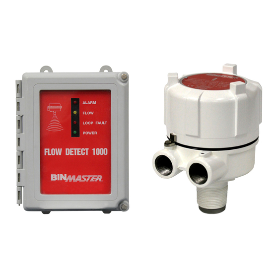
MODEL FDS1000 DESCRIPTION The Flow Detect 1000 is an industrial instrument that senses flow or no-flow conditions of solids and powders in pneumatic pipelines, gravity chutes and feeders. It uses microwave doppler technology to provide highly sensitive motion detection. The sensor probe is completely non-intrusive, avoiding contact with the flow stream and associ- ated wear problems. -
Page 5: Installation Considerations
INSTALLATION CONSIDERATIONS The FDS1000 Sensor is approved as intrinsically safe for Class II Groups E, F, & G when used with the FDC1000 Control unit. The FDC1000 Control unit serves as the Intrinsic Safe Barrier between the high-energy circuits of the 120VAC input and relay contact circuits, and the safe low energy connection to the remote FDS1000 sensor. - Page 6 Jamieson Equipment Company www.jamiesonequipment.com toll free 800.875.0280...
-
Page 7: Wiring Power And Relay Circuits
WIRING OF POWER AND RELAY CIRCUITS The NEMA 4X enclosure is not supplied with a conduit opening to accommodate the power and relay wiring. The placement and size of this opening depends upon specific installation needs and is left to the discretion of the installing electrician. -
Page 8: Wiring Between Fdc1000 - Fds1000
WIRING BETWEEN FDC1000 AND FDS1000 The FDC1000 control unit serves as an intrinsically safe barrier providing low energy output circuits to the FDS1000 sensor. A five-conductor cable is required for interconnection. Simply connect each wire of the cable to corresponding terminals in the sensor and control units as shown in Figure 3. Wire size of at least 18AWG is suit- able for distances up to 1500 feet, and 16AWG for distances up to 2500 feet. -
Page 9: Sensitivity Adjustment Procedure
Sensitivity Adjustment Procedure: Start with the ADJ control turned full counter clock wise to the 7 o’clock position. With no material flowing, FLOW light off, turn the ADJ control clockwise to the point where the FLOW light just turns on and note this position. This will normally be the 3 o’clock position. Start material flowing. -
Page 10: Troubleshooting
Verify the setting of alarm (relay operation) delay for FLOW and NO FLOW. For troubleshooting it is often convenient to use short delays. MAINTENANCE The FDS1000 sensor and FDC1000 control are to be serviced by the BinMaster Division of Garner Industries only. For service information call 1-800-278-4241. WARNING: The FDS1000 sensor is an intentional radiator of RF energy, certified under Part 15 of the FCC Rules. - Page 11 Mounting Instructions Always Mount Unit With Conduit opening down Conduit Seal When installing this level indicator in environments where it is possible for moisture or moist air to enter the enclosure through the electrical conduit, the conduit opening should be sealed with a duct seal compound or putty appropriate for the purpose.
Need help?
Do you have a question about the 1000 and is the answer not in the manual?
Questions and answers