
Related Manuals for BINMASTER 3DLevelScanner-MVL


Summary of Contents for BINMASTER 3DLevelScanner-MVL
- Page 1 3DLevelScanner S-M-MV & HE Models Operating Instructions > Non-contact > Dust-penetrating > Multiple-point measurement > Optional 3D visualization www.binmaster.com...
-
Page 2: Table Of Contents
DIFFERENT CONNECTION METHODS ..............21 4-20 ..................... 21 ONNECTION HART C ..................21 OMMUNICATION RS-485 C ..................22 OMMUNICATION ..............22 OMMUNICATION USING THE TCP/IP C ..................22 OMMUNICATION APPENDIX A: ONBOARD CONFIGURATION ..............23 3DLevelScanner Operating Instructions © 2012 BinMaster all rights reserved... - Page 3 ESET APPENDIX B: MAINTENANCE ..................28 APPENDIX C: RECOMMENDED TOOLS ................. 29 APPENDIX D: SPECIFICATIONS ..................30 ........................ 30 ECHNICAL DATA ........................33 IMENSIONS APPENDIX E: STANDARDS & APPROVALS ..............35 3DLevelScanner Operating Instructions © 2012 BinMaster all rights reserved...
-
Page 4: About This Document
If the 3DLevelScanner is used in a manner not specified in this manual, the protection provided by the 3DLevelScanner will be impaired. 3DLevelScanner Operating Instructions © 2012 BinMaster all rights reserved... -
Page 5: Storage And Transport
Storage and transport The scanner is protected by special packaging during transport, and is guaranteed to handle normal loads during transport. 3DLevelScanner Operating Instructions © 2012 BinMaster all rights reserved... -
Page 6: 3Dlevelscannerᵀᴹ Overview
3DLevelScannerᵀᴹ Overview Theory of Operation The BinMaster 3DLevelScanner™ is the only device available which delivers accurate measurement of bulk solids and powders – regardless of material type, product characteristics, storage silo type, size, bin or container, and harshness of the storage environment. -
Page 7: Models
All references in this manual to the 3DLevelScanner can be referred to as 3DLevelScanner or simply the scanner, if nothing else is mentioned it applies to any of the scanner’s models. 3DLevelScanner Operating Instructions © 2012 BinMaster all rights reserved... -
Page 8: Physical Installation
BinMaster strongly recommends installing the 3DLevelScanner according to the 3DScanner Locator PC software for properly choosing installation location and positioning. - Page 9 The scanner cannot be mounted at a distance lower than 500mm (16") from the wall. When choosing the installation location, consider the filling and emptying points. Use the 3D Scanner Locator PC software for choosing a proper location. 3DLevelScanner Operating Instructions © 2012 BinMaster all rights reserved...
-
Page 10: Scanner Orientation
This comment applies 3DLevelScanner models including the S model. Wrong Correct 3DLevelScanner Operating Instructions © 2012 BinMaster all rights reserved... -
Page 11: Site Preparations
A 24VDC (1.5 Watt) power supply must be prepared and ready to use near the scanner mounting location. The 3DLevelScanner is a 4-Wire device. The voltage supply and data output (4- 20mA) are carried along two separated two-wire connection cables. 3DLevelScanner Operating Instructions © 2012 BinMaster all rights reserved... -
Page 12: Assembly And Mounting
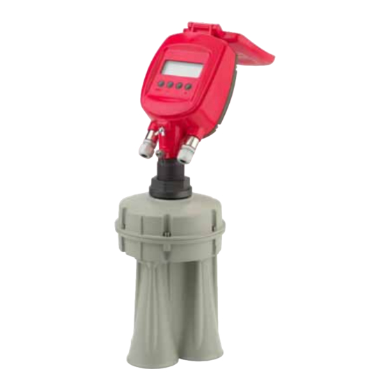
3DLevelScanner Body: Includes three antennas, transducers and temperature sensor. The flange is mounted on the body and tightened to it. 3DLevelScanner Head: Includes the electronic board and all wiring connections. The Head is mounted on the body. 3DLevelScanner Operating Instructions © 2012 BinMaster all rights reserved... - Page 13 Prior to the installation of the 3DLevelScanner, an installation flange should be prepared. The flange must have a 52mm (2.05") hole for the scanner body thread insertion. BinMaster provides two types of standard flanges. Please refer to page 28: Appendix B: Accessories for flange specifications. Installing the Flange Verify the O-Ring Use 18 "...
- Page 14 NOTE: The 3DLevelScanner head may be installed in six different positions. Tighten the front screw using a 4mm hex key and a 13mm wrench. Replace the cable clamp back to position, between the antenna cable and the electronic board. 3DLevelScanner Operating Instructions © 2012 BinMaster all rights reserved...
-
Page 15: Wiring
In hazardous areas you should take note of the appropriate regulations, conformity and type of approval certificates of the sensors and power supply units. Refer to the printed safety manual provided with the ATEX/FM approved 3DLevelScanner. 3DLevelScanner Operating Instructions © 2012 BinMaster all rights reserved... - Page 16 (A3/32") screwdriver. Insert the wire edges into the terminals according to the wiring plan detailed next, and fasten the terminal screws. Gently pull the wires to ensure they are securely connected. 3DLevelScanner Operating Instructions © 2012 BinMaster all rights reserved...
- Page 17 Tighten the compression nut over the cable gland entry opening. Verify that the sealing ring completely wraps the cable. IMPORTANT: Gland compression nut tightening provides good sealing. It is necessary for the scanner to maintain IP67 requirements, and for extended scanner lifetime. 3DLevelScanner Operating Instructions © 2012 BinMaster all rights reserved...
- Page 18 The PS ports in the right connector are Power Supply OUT. Do not plug IN power supply in these ports. WARNING: The 4-20mA / HART lines should NOT be connected using multidrop. 3DLevelScanner Operating Instructions © 2012 BinMaster all rights reserved...
-
Page 19: First-Time Activation
Configuration and adjustment of the 3DLevelScanner must be done using the 3DLevelManager software, with the optional addition of GSM/GPRS communications using 3DLinkPro. For detailed configuration procedure, refer to the BinMaster 3DLevelManager Software Manual and the 3DLinkPro Manual. The 3DLevelScanner User Interface... -
Page 20: Switching On The Scanner
By default, when the name has not been configured yet, this line remains empty. Press to return to the Main Menu. Press for 3 seconds to switch to the basic measurement screen. 3DLevelScanner Operating Instructions © 2012 BinMaster all rights reserved... -
Page 21: First-Time Activation Steps Summary
Polling Address digits. Use the key to modify the value. The default polling address is 00. The polling address range from 00 to 63. Press to store the modified address. 3DLevelScanner Operating Instructions © 2012 BinMaster all rights reserved... -
Page 22: Different Connection Methods
Using the 3DLevelManager for communicating with the 3DLevelScanner allows the user to choose several communication types: RS-485, HART, GSM, GPRS and TCP/IP, for more information and details regarding the communications, refer to the BinMaster 3DLevelManger Software Instructions manual. 4-20mA Connection The 3DLevelScanner outputs the % of Volume as set in the configuration and between the Full and Empty calibration levels. -
Page 23: Rs-485 Communication
The RS-485 bus can be converted to TCP/IP communication. TCP/IP to RS4585 converter installation should be done as with any scanner, including the resistors and daisy-chain considerations. NOTE: Consult with BinMaster Technical Support team for assistance on the proper TCP/IP converter to use. 3DLevelScanner Operating Instructions © 2012 BinMaster all rights reserved... -
Page 24: Appendix A: Onboard Configuration
Navigate up/down the menu using the Measured Params. keys, and Press to select the desired option. →Distance Level Volume Measurement Distance settings Measured Params. →Distance Select the Distance option and press proceed. Level Volume 3DLevelScanner Operating Instructions © 2012 BinMaster all rights reserved... - Page 25 Select the Analog Output option from the Level Measured Params. Menu. Press to proceed. Volume →Analog Output The Measured Parameter screen is shown, Measured Parameter displaying the Analog Output value in mA. 20.0mA Ang. Out. ██████████████████████ test 3DLevelScanner Operating Instructions © 2012 BinMaster all rights reserved...
-
Page 26: Display Settings
This function allows setting a Tag Name for the current scanner. At the Main Menu, navigate down using the Main Menu to select Display Settings, and Press Extended Calibr. proceed. Output Settings →Display Settings 3DLevelScanner Operating Instructions © 2012 BinMaster all rights reserved... -
Page 27: Device Info
The screen displays the Firmware Version Firmware Version of the scanner. Press to proceed. The screen displays the Hardware HW Interface communications interface information for the 4...20mA/HART scanner. Modbus Press to proceed. RS485 3DLevelScanner Operating Instructions © 2012 BinMaster all rights reserved... -
Page 28: Device Reset
No? to cancel reset. Press proceed. A Yes? selection will cause the scanner to reset and restart. A No? selection will cause the display to switch back to the Main Menu. 3DLevelScanner Operating Instructions © 2012 BinMaster all rights reserved... -
Page 29: Appendix B: Maintenance
Appendix B: Maintenance Preventive maintenance procedure BinMaster recommends the following periodical maintenance procedure for keeping the scanner in proper operating conditions and preventing unnecessary malfunctioning which may be caused by environmental factors over time: Clean the interior part of the antennas (see details below) ... -
Page 30: Appendix C: Recommended Tools
RS-485 to USB converter, including drivers 120Ohm and 250Ohm resistors PC/Laptop Internet GSM Stick (for testing communications between the installed scanner and the monitoring computer at the center, using the 3DLinkPro). 3DLevelScanner Operating Instructions © 2012 BinMaster all rights reserved... -
Page 31: Appendix D: Specifications
Accessory kit with additional M20x1.5 cable gland and 2 x NPT1/2” adaptors Display panel Display LCD 4 lines x 20 characters Adjustment elements 4 keys (ESC, +, -, E) Load 4-wire sensor See load diagram bellow Integration time 0…9999 s, adjustable 3DLevelScanner Operating Instructions © 2012 BinMaster all rights reserved... - Page 32 The power supply must be a limited power source type with maximum output current 1A and voltage range of 20VDC minimum and 32VDC maximum, and not to be connected to a DC distribution network. 3DLevelScanner Operating Instructions © 2012 BinMaster all rights reserved...
- Page 33 The 3DLevelScanner complies with Part 15 of the FCC Rules. Operation is subject to the following two conditions: (1) this device may not cause harmful interference, and (2) this device must accept any interference received, including interference that may cause undesired operation. 3DLevelScanner Operating Instructions © 2012 BinMaster all rights reserved...
-
Page 34: Dimensions
Appendix D: Specifications ● Dimensions Dimensions 3DLevelScanner dimensions: Front view 3DLevelScanner Operating Instructions © 2012 BinMaster all rights reserved... - Page 35 Appendix D: Specifications ● Dimensions 3DLevelScanner dimensions: Side view 3DLevelScanner Operating Instructions © 2012 BinMaster all rights reserved...
-
Page 36: Appendix E: Standards & Approvals
Appendix E: Standards & Approvals 3DLevelScanner EMC Test Certificate for FCC Part 15, Sub-part B, Class A 3DLevelScanner Operating Instructions © 2012 BinMaster all rights reserved... - Page 37 IEC 61000-4-3: 2002 80-1000MHz, 1V/m; 1.4-2GHz, 1V.m; 2.0-2.7GHz, 1V/m IEC 61000-4-4: 2004 Power Lines: 1kV; Signal Lines: 0.5kV IEC 61000-4-6: 2004 0.15-80MHz 1VRMS, 80% A.M. by 1kHz Power & Signal Lines 3DLevelScanner Operating Instructions © 2012 BinMaster all rights reserved...
- Page 38 P.O. Box 29709 Featuring APM Lincoln, NE 68507 Lincoln, NE 68529 Automation Solutions Ltd Technologies 800.278.4241 | 402.434.9102 (patent pending) Fax: 402.434.9133 www.binmaster.com | info@binmaster.com ©2012 BinMaster Level Controls. All rights reserved. Information in this document is subject to change without notice.
Need help?
Do you have a question about the 3DLevelScanner-MVL and is the answer not in the manual?
Questions and answers