
Related Manuals for Pylontech RT12100


Summary of Contents for Pylontech RT12100
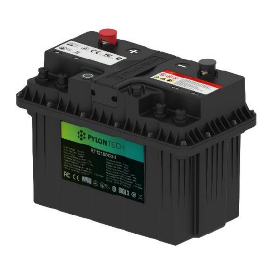
- Page 1 LFP Lithium Ion Battery System RT12100G31 Operation Manual UL version Information Version: UL22RT12010602 5PMPA08-00122...
-
Page 3: Table Of Contents
This manual introduces RT12100G31 from Pylontech. Please read this manual before install the battery and follow the instruction carefully during the installation process. Any confusion, please contact Pylontech immediately for advice and clarification. Symbol in Label, Manual and Product Safety / Sécurité... -
Page 4: Symbol In Label, Manual And Product
1. Symbol in Label, Manual and Product Do not reverse connection the positive and negative. N'inversez pas la connexion positive et négative. Do not place near open flame. Ne pas placer près d'une flamme nue. Do not place at the children and pet touchable area. Ne placez pas l'appareil dans la zone de contact des enfants et des animaux domestiques. - Page 5 Certification Mark for the U.S Market Certification Mark for the EU Market Recycle label. Label for Waste Electrical and Electronic Equipment (WEEE) Directive (2006/66/EC) and its amendments The certificate label for Bluetooth SIG. The Bluetooth Certification Mark for Japanese market. The TUV Mark certificate label for Safety Testing (EN62619) by TÜ...
-
Page 6: Safety / Sécurité
Sécurité Safety / The RT12100G31 is operated by authorized person only. Read all safety instructions carefully prior to any work and observe them at all times when working on with the system. RT12100G31 opéré uniquement par le personnel autorisé. Lisez attentivement toutes les instructions de sécurité... - Page 7 Symbol/Symbole Lethal voltage! Tension mortelle! Battery strings will produce high voltage DC power and can cause a lethal voltage and an electric shock. La batterie produira un courant continu à haute tension et Danger peuvent provoquer une tension mortelle et un choc Danger électrique.
- Page 8 Batteries deliver electric power, resulting in burns or a fire hazard when they are short circuited, or wrongly installed. Les piles fournissent de l'énergie électrique, ce qui entraî ne des brûlures ou un risque d'incendie lorsqu'elles sont court-circuitées ou mal installées. Lethal voltages are present in the battery terminals and cables.
- Page 9 Warning Avertissement Do not open or deform the battery module; It is prohibited to disassemble the battery (QC tab removed or damaged). Ne pas ouvrir ou déformer le module de batterie; Il est interdit de démonter la batterie (languette QC retirée ou endommagée). For battery installation, the installer shall refer to NFPA70 standard for operation.
- Page 10 Caution Attention Improper settings or maintenance can permanently damage the battery. Incorrect inverter parameters will lead to the premature aging of battery. Le réglage ou la maintenance incorrecte peuvent endommager en permanence la batterie. Les paramètres de l’inverseur incorrects entraîneront un vieillissement prématuré...
- Page 11 It is prohibited to connect the battery with different type of battery. Il est interdit de connecter la batterie à une batterie de différent type. Please do not open, repair or disassemble the battery except staffs from Pylontech or authorized by Pylontech. We do not undertake any consequences or related responsibility which because of violation of safety operation or violating of design, production and equipment safety standards.
-
Page 12: Introduction
3. Introduction RT12100G31 is a lithium iron phosphate battery module used to replace the typical lead-acid battery. The battery can be charged by solar power, diesel generator, and utility power via relevant AC/DC converter. The battery can be used for energy storage and providing back-up power for typical electrical appliances. -
Page 13: Specification
3.2 Specification RT12100G31 Battery Dimension... - Page 14 Basic Parameters Value Nominal Voltage (V) 12.8 Nominal Capacity (Ah) Dimension (mm) 325(L)*173.5(W)*226(H) Weight (Kg) 12±0.2 Discharge Voltage Range (Vdc) 10.8~14.4 Recommended Charge Voltage (Vdc) 14~14.4 Recommend Charge/Discharge Current (A) Max. Continue Charge/Discharge Current Peak Discharge Current (A) 200@30sec 500Kbps RS485 default for console, 115200bps Communication...
-
Page 15: Panel
3.3 Panel RT12100G31 Panel Description 3.4 Equipment Interface Instruction Power Button Power button pressed: ready to turn on. Power button pops back: power off. For storage or shipping. LED Status Indicators: Power on/Normal Flash 1, OFF 1.5S, on 0.5s Waiting Addressing Flash 2,OFF 1s, on 1s Communication time out... - Page 16 External Communication Interface (Dry contact and COM port) Dry Contact IN1+ IN1- IN2+ CANH COM1 CANL IN2- RS485A COM2 RS485B PIN Assignments Front View of Cable Dry Contact Definition: Pin1 Input, passive signal. Close: Enable Heater function. Open Disable Heater function Pin2 Pin3 Input, passive signal.
- Page 17 Notes: 1. Input signals should be passive signals. 2. The voltage value of output signal is less than 25V, and the current value is less than 10mA. CAN(COM) 500 Kbps. 120Ω terminal resistance. RS485/Console(COM) For manufacturer or professional engineer to debug or service. Default Communication speed 115200 bps.
-
Page 18: Safe Handling Guide
4. Safe Handling Guide 4.1 Schematic Diagram of Solution... -
Page 19: Danger Label
4.2 Danger Label 4.3 Tools Wire cutter Screwdriver NOTE Use properly insulated tools to prevent accidental electric shock or short circuits. If insulated tools are not available, cover the entire exposed metal surfaces of the available tools, except their tips, with electrical tape. 4.4 Safety Gear It is recommended to wear the following safety gear when dealing with the battery... - Page 20 pack. Insulated gloves Safety goggles...
-
Page 21: Installation And Operation
5. Installation and Operation 5.1 General Guidance ⚫ All batteries must be connected in parallel before series connection. Please make sure the modules are having less than 0.1Vdc voltage difference between each other, or ideally fully charge the modules in parallel, before connecting them in serial to avoid capacity imbalance. -
Page 22: Package Items
otherwise it will affect the Bluetooth signal strength. ⚫ When multiple batteries are connected in series or parallel, it is possible to work without connecting the communication cable between the batteries to an upper controller but it is required to connect the internal communication cable in order to ensure the consistency of SOC and better performance of the batteries. - Page 23 Internal Length(M) Description Communication For internal serial connection between batteries Cable Pin assignment Link 0 Link 1 3 ~ 8 is pin - pin 1 set of Dry contactor heater terminal Description Dry Contact Insert into the I/O port on the master battery, the heater feature Heater Terminal will be enabled to automatically function when necessary.
- Page 24 Spare Description communication Empty comm. terminal acting as spare part or further insert terminal comm. cable to connect to upper controller. 2) For External Cable Kits: NOTE External Cable Kit, NOT included in battery carton box. It`s acting as an option for customer to purchase relevant power/comm. cable to connect to the inverter.
- Page 25 Length(M) Power Cable Positive 4AWG, WI0PRT121266 WI0PRT121267 WI0PRT121268 WI0PRT121269 (Orange) GT25-8 Negative Terminals WI0PRT121262 WI0PRT121263 WI0PRT121264 WI0PRT121265 (Black) b. Internal Communication cable Length(M) Internal Communication cable CAT6, Black, 2*ALTW M12 WI0SRT121171 WI0SRT121255 WI0SRT121256 WI0SRT121257 Connector External Communication Cable...
-
Page 26: Installation Location
Length(M) External Communication Cable CAT6, Black, ALTW M12 Connector WI0SRT121258 WI0SRT121259 WI0SRT121260 WI0SRT121261 5.3 Installation Location Make sure that the installation location meets the following conditions: The floor is flat and level;... - Page 27 There are no flammable or explosive materials; The ambient temperature is within the range from -40°C to 60°C; The temperature and humidity is maintained at a constant level; The installation areas shall avoid of direct sunlight; There are no mandatory ventilation requirements for battery module, but please avoid of installation in confined area.
-
Page 28: Installation Method Of Multiple Batteries
5.4 Installation Method of Multiple Batteries The battery can be placed flexibly according to the actual site environment. If the battery is placed on a vehicle or a mobile object, the battery needs to be well fixed. The upper surface of the battery is flat, the battery and the vehicle can be fixed with a pressure strip in the horizontal or vertical direction. - Page 29 Series Configuration Recommended Charge Discharge Voltage Range Voltage Value (Vdc) (Vdc) 14 ~ 14.4 10.8 ~ 14.4 28 ~ 28.5 22~ 28.5 42~ 43 33 ~ 43 56 ~ 57 44 ~ 57 Parallel Configuration Maximum Charge /Discharge Current Value 1~8P 100A*N ( N= module amount, 1~8) 9P~16P...
-
Page 30: Production And Adjustment Of Communication Plugs
5.5 Production and Adjustment of Communication Plugs 1) The communication plug can be flexibly adjusted to the direction of actual placement of the battery during installation, follow below procedure. Align the plugs and sockets with the Navigation key (1) and insert the plugs. Fasten the screw (2) to secure the plug. - Page 31 All the installation and operation must follow local electric standard. L’installation et l’opération doivent respecter les normes électriques locales. After installation, do not forget to register online for full warranty: http://www.pylontech.com.cn/service/support Warning Avertissement The power cables’ current capacity is 120A max. If the battery string’s design current over 100A, it must configure 2 pairs of external power cables to extend current capacity.
-
Page 32: Power On
5.6 Power on Double check all the power cable and communication cable. 1) The one with empty Link Port 0 is the Master Battery Module, others are slaves (1 master battery configure with maximum 15 slave batteries). 2) Switch on (press Power Button) all the battery modules from last battery to the 1st battery. -
Page 33: Power Off
Description Dry Contact After power on the system, insert into the I/O port on the master Heater Terminal battery, the heater feature will be enabled to automatically function when necessary. Note: 1) After the battery module powered on, the pre-charge circuit of the battery will last for 300mS to ensure current-limited charging to the capacitor of external load/charger. -
Page 34: Trouble Shooting
6. Trouble Shooting ① Single device power on Symptom: Button switch pressed, the indicator does not light Inspection steps: (1) measure the output voltage of battery with multimeter to check whether the battery has output or not, if so this means that only the indicator is malfunction. (2) pop-up the button switch 2s and then press again, observe whether the indicator light is on or flashing - to check whether it`s a button poor connection. - Page 35 Symptom: After the first device is powered on (Press the button to start or Voltage Activated Circuit), only some of the devices are powered on successfully (light blinks). Inspection steps: (1) According to the communication cable wiring order, if a device and its subsequent devices fail to power on, please check if the communication cable between the device and the previous device is loose, misconnected or if the wire is broken.
- Page 36 The indicator flashes (1s on and 1s off) or via close-loop communication, the host computer indicates address assignment failure. Inspection steps: (1) First check whether the number of cascade units exceeds 16pcs - product design only supports a maximum of 16 cascade units. (2) Then check whether the cascade is connected in the correct order - the correct order is the previous module link1 to the next module link0.
-
Page 37: Emergency Situations
will notify all devices to enter hibernation after the under-voltage protection, or the first unit will notify all devices to enter hibernation forcibly when it monitors the under-voltage protection state before other devices are offline, at which time it is necessary to access the power supply to activate the device and charge it. -
Page 38: Remarks
3) Wet Batteries If the battery pack is wet or submerged in water, do not let people access it, and then contact Pylontech or an authorized dealer for technical support. Cut off all power switch on inverter side. 4) Damaged Batteries Damaged batteries are dangerous and must be handled with the utmost care. - Page 39 European Union) to process, and using the best available techniques to achieve a relevant recycling efficiency. Storage, Maintenance and Expansion 1) It is required to charge the battery at least once every 6 months, for this charge maintenance make sure the SOC is charged to higher than 90%. 2) Every year after installation.
-
Page 40: About Fcc
9. About FCC FCC Regulations: ⚫ This device complies with part 15 of the FCC Rules. Operation is subject to the following two conditions: (1) This device may not cause harmful interference, and (2) this device must accept any interference received, including interference that may cause undesired operation. - Page 41 FCC RF Radiation Exposure Statement This equipment complies with FCC radiation exposure limits set forth for an uncontrolled environment. To comply with FCC RF Exposure compliance requirements, this grant is applicable to only Mobile Configurations. The antennas used for the transmitter must be installed to provide a separation distance of at least 20cm from all persons and must not be co-located or operating in conjunction with any other antenna or transmitter.
- Page 44 Pylon Technologies Co., Ltd. No. 73, Lane 887, ZuChongzhi Road, Zhangjiang Hi-Tech Park Pudong, Shanghai 201203, China T+86-21-51317699 | +86-21-51317698 service@pylontech.com.cn www.pylontech.com.cn...
Need help?
Do you have a question about the RT12100 and is the answer not in the manual?
Questions and answers