Table of Contents
Advertisement
Quick Links
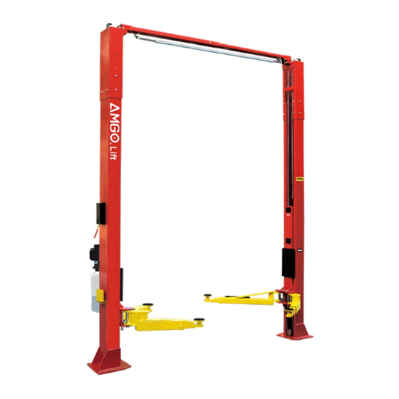
DIRECT-DRIVE TWO POST LIFT
Cargo Claims
If there is any missing or damaged
product during transportation, the
buyer must notate on the shipping
paperwork or refuse the shipment.
NOTATE ALL DAMAGE OR REFUSE
DAMAGED SHIPMENT!
Model: OHX-10
OHX-10H
△
DANGER
!
Read the entire contents of this manual before
using this product. Failure to follow instructions
and safety precautions could result in serious
injury or even death. Make sure all other
operators also read this manual. Keep this
manual near the machine so that it can be seen
by all users. By proceeding with installation and
operation, you agree that you are fully
understand the contents of this manual and take
full responsibility for the use of the product.
Advertisement
Table of Contents

Related Manuals for AMGO Hydraulics OHX-10


Summary of Contents for AMGO Hydraulics OHX-10
- Page 1 DIRECT-DRIVE TWO POST LIFT Model: OHX-10 OHX-10H △ DANGER Read the entire contents of this manual before using this product. Failure to follow instructions and safety precautions could result in serious Cargo Claims injury or even death. Make sure all other If there is any missing or damaged operators also read this manual.
-
Page 2: Table Of Contents
CONTENTS PROFILE ..........................1 IMPORTANT SAFETY INSTRUCTIONS ................ 3 I. PRODUCT FEATURES AND SPECIFICATIONS ............ 5 II. INSTALLATION REQUIREMENT ................9 III. INSTALLATION STEPS ................... 12 IV. EXPLODED VIEW ...................... 40 V. TEST RUN ........................48 VI. OPERATION INSTRUCTIONS ................50 VII. -
Page 3: Profile
PROFILE The two post lift is a commonly used vehicle repair and maintenance tool that uses a pneumatic hydraulic or electric system that can lift the car up to a certain height so that the vehicle can be placed in a suitable position for inspection and repair. Car lifts can be divided into pneumatic and electric, which have the characteristics of safe and reliable, simple structure and quick installation. -
Page 5: Important Safety Instructions
IMPORTANT SAFETY INSTRUCTIONS In order to properly maintain your product and ensure operator safety, it is the responsibility of the product owner to read and follow these instructions! 1. Ensure product installation complies with all applicable local regulations and rules, such as Occupational Safety and Health Administration regulations and electrical codes. - Page 6 placed in the lounge or basement. 16. Maintain with care. Keep the machine clean for better and safer operation. Perform proper lubrication and maintenance procedures according to the manual. Keep handles or buttons clean, dry, and free of oil. 17. Stay alert. Use common sense to observe what you are doing and stay alert. 18.
-
Page 7: Product Features And Specifications
I. PRODUCT FEATURES AND SPECIFICATIONS Model: OHX-10 · Direct-drive design, minimize the lift wear parts and breakdown ratio; · Dual hydraulic cylinders are designed and manufactured according to high standard, utilizing imported seals; · Self- lubricating UHMW Polyethylene sliders and bronze bush;... - Page 8 Model OHX-10H · Direct-drive design, minimize the lift wear parts and breakdown ratio; · Dual hydraulic cylinders are designed and manufactured according to high standard, utilizing imported seals; · Self- lubricating UHMW Polyethylene sliders and bronze bush; · Single-point safety release with dual safety design; .
- Page 9 Arm Swings View 99-13/16” / 105 11/16” 15/16"-140 7/8” Car in direction...
- Page 10 Fig. 3 Fig. 3 Important note Follow the instructions to ensure proper installation or operation of your lift. Failure to follow these instructions may result in serious body injuries and not not under warranty. The manufacturer is not liable for any form of loss or damage caused directly or indirectly by incorrect installation or operation of this product.
-
Page 11: Installation Requirement
II. INSTALLATION REQUIREMENT TOOLS REQUIRED Rotary Hammer Drill (Φ3/4) Carpenter’s Chalk Hammer Screw Sets Level Bar Tape Measure (295”) English Spanner (12") Pliers Wrench set : (10 Lock Wrench # #... - Page 12 Equipment storage and installation requirements. 1.Store the equipment in a dry, non-moldy, non-flammable environment. 2.The lift is only approved for indoor installation and use, and outdoor installation is prohibited. 3.When installing the device, take safety precautions according to the instructions to avoid device damage.
- Page 13 Concrete must be 3,000psi minimum Fig. 7 POWER SUPPLY 1. You are required to use a licensed and qualified electrician for the installation process. 2. The power supply requires 220VAC, with a cord larger than 12AWG, and must be properly grounded. △...
-
Page 14: Installation Steps
4. Floor: Install lift only on flat concrete floor. Do not install on asphalt or any other surface. Installation ceiling height requirement: OHX-10›144” OHX-10H›157” Fig. 8 △ CAUTION Installing the lift on a surface with slopes more than 3° could lead to injury or even death. - Page 15 B. Use a carpenter’s chalk line to establish installation layout of base-plate (See Fig.9). Click a line Fig. 9 C. Check the parts before assembly. 1. Packaged lift and hydraulic power unit ( See Fig. 10). Fig. 10 2. Move aside the lift with fork lift or hoist, open the package, take out the parts above/in upper outer column, check the parts according to the shipment parts list (See Fig.11).
- Page 16 5. Open the parts bag 1 and check the parts according to parts box list (See Fig. 14). Parts Bag 1 Fig. 14 6. Open the Parts Bag 2 of parts and check the parts according to parts bag list (See Fig. & 16). Fig. 15 Parts Bag 2 OHX-10 Accessories...
- Page 17 Parts Bag 2 Fig. 16 OHX-10H Accessories D. Place the two columns in parallel on the ground of installation position, and determine the installation position of the power side column according to the condition of the installation site. Under normal circumstances, the power side column is installed on the right side of the entering direction;...
- Page 18 E. Install the cylinder and connect the oil hose to the cylinder. Install cylinder fitting After installation Fig.18 and oil hose Install column parts. 1. OHX-10 installation of column parts Fig.19 & 20. A View B View Off side column Power side column Fig. 19 Fig.
- Page 19 2. OHX-10H installation of outer column parts. Fig. 21 A Magnified view Off side outer column Fig.21 Power side outer column...
- Page 20 2.1 Place the two columns in parallel on the ground of the installation position, and determine the installation position of the power-side column according to the condition of the installation site. Under normal circumstances, the power side column is installed on the right side of the entering direction;...
- Page 21 (See Fig. 23) G. Column plumbness adjustment. 1. OHX-10 Erect the columns on installation layout of base plate, install the anchor bolts. Check the columns plumpness with level bar, and adjust with shims if the columns are not vertical. Do not tighten anchor bolts yet.
- Page 22 2. OHX-10H Erect the columns on installation layout of base plate, install the anchor bolts. Check the columns plumpness with level bar, and adjust with shims if the columns are not vertical. Do not tighten anchor bolts yet. (See Fig. 24) Width: 112-1/4”...
- Page 23 H. Install top beam (See Fig. 25) 1. Hang the hook of top beam(with limit switch) on the power side outer column, then align the holes and install the bolts. Install the top beam(with limit switch) to the power side column Fig.25...
- Page 24 After install the other top beam on off side outer column, bolt both top beams and tighten all the bolts. (See Fig. 26) Only OHX-10H Only select this group of holes when installing with the width extension kit. Select this group of holes to install top beams.
- Page 25 I. Install the limit switch control bar (See Fig. 27). Install the limit switch control bar to the support brackets as shown below Off side Power side Loosen the bolt slightly, adjust the distance between the two control bar support bracket till the control bar can rolls smoothly, then tighten the bolts.
- Page 26 J. Install cables. Raise up the carriages and lock at the same level of safety lock. 1. OHX-10 cable connection. Pass the cable from the bottom of the carriage to the carriage window, then screw up the 2 cable nuts together.
- Page 27 2. OHX-10H cable connection. 2.1 OHX-10H cable connection of high setting(see fig 29). Pass the cable from the bottom of the carriage to the carriage window, then screw up the 2 cable nuts together. High setting Screw two cable nuts Fig.
- Page 28 2.2 OHX-10H cable connection of low setting (See Fig. 30). Note: pass the cable through the inside of carriage. (Low setting) Fig.30...
- Page 29 K. Install oil hose assy, tighten all oil hose fittings. 1. OHX-10 oil-line connecting diagram(See Fig.31) A Magnified view Fig.31...
- Page 30 2. OHX-10H oil-line connecting diagram (See Fig. 32). 84、85 only used for high setting, not required for low setting. A Magnified view Fig.32...
- Page 31 3. Follow below steps to connect power unit oil hoses. (See Fig. 33) Left outlet port Right outlet port Socket plug Disassemble the socket plug. Assemble 90 fitting of power unit, and connecting the oil hose. Red Plug Disassemble left plastic red plug. Assemble the socket plug by Step A to this left oil outlet port.
- Page 32 L. Lock release cable connecting diagram (See Fig. 34) Wearing wire cable A side B side Fig.34...
- Page 33 Note: Don’t cross the oil hose and lock release cable (See Fig. 35, 36 & 37). Safety Cable Oil hose Power side Off side Fig. 35 Fig. 36 Lock release cable Oil hose across outside of wire clamp Wire cable for limit switch Fig.37 M.
- Page 34 Engagement of moon gear and arm lock: Lower the carriages down to the lowest position, use socket head wrench to loosen the socket bolt follow the arrow direction to adjust the moon (See Fig. 39), gear ; tighten the bolts after the moon gear and arm lock are engaged (See Fig.
- Page 35 2. Connecting limit switch wire: remove the short wire connecting terminal 4# of control button and A2 of AC contactor firstly (See Fig.44), then according to the wire number of the limit switch, connect them respectively to terminal 4# of control button and A2# of AC contactor.
- Page 36 △ DANGER All wiring must be performed by a licensed, certified Electrician. Do not perform any maintenance or installation of the lift without first ensuring that the main power supply has been disconnected from the lift and that it cannot be re-energized until all procedures have been completed.
- Page 37 2. OHX-10 width extension kits installation. 2.1 Oil-line connection diagram 118-1/8” Fig.47...
- Page 38 2.2 OHX-10 sync cables connection Pass the cable from the bottom of the carriage to the carriage window, then screw up the 2 cable nuts together. (See Fig. 48). Screw the two cable nuts Fig.48 Optional parts list OHX-10 Item...
- Page 39 3. OHX-10H width extension kits installation. 3.1 Oil-line connection diagram 118-1/8” 118-1/8” Fig.49...
- Page 40 3.2 OHX-10H sync cable assy. connection for low setting. (Fig. 50) Note: pass the cable through the inside of carriage. Low setting Fig.50...
- Page 41 3.3 OHX-10H sync cable assy. connection for high setting (Fig. 51). Pass the cable from the bottom of the carriage to the carriage window, then screw up the 2 cable nuts together. Screw the two cable nuts Fig.51 Optional parts list OHX-10H Item Part#...
-
Page 42: Exploded View
IV. EXPLODED VIEW OHX-10 Fig. 52... - Page 43 OHX-10H Fig. 53...
- Page 44 PARTS LIST FOR OHX-10 and OHX-10H QTY. Item Part# Description OHX-10 OHX-10H 10209125 Hex bolt M10*30 10209039 Lock washer φ10 10209022 Flat washer φ10 10209021 Hex nut M10 10209009 Round head bolt M6*8 10209008 Safety device protective cover 10209010 Clip ring (φ10)
- Page 45 QTY. Item Part# Description OHX-10 OHX-10H 10209015 Slider block 10209016 Carriage plastic cover 1102563000A Carriage 10209018 Protection rubber 10209019 Flat screw M6*16 10520023 Clip ring φ38 11217168 Arm pin 11217046A Arm lock handle (Left) 10206050A Spring 11217046 Arm lock handle (Right)
- Page 46 QTY. Item Part# Description OHX-10 OHX-10H 11209053B Stackable adapter (5”) 11209054A Stackable adapter bracket 10680003 Hex bolt M8*12 10209059 Anchor bolt 3/4*5-1/2 10201090 Shim(3/64”) 10620065 Shim(5/64”) 10209066 Hex Nut M16 1002561004 Sync cable assy. 3/8”x 379 1/2” 1002571005 Sync cable assy. 3/8”x 427 9/16”...
- Page 47 4.1 Rear arm assy. (10279011) exploded view Fig.54 Item Part# Description QTY. 10206048 Socket bolt M10*30 10209039 Lock washer φ10 10209022 Flat washer φ10 11206049 Moon gear 11206192 Outer arm 10201149 Round head bolt M8*12 11206193 Inner arm 4.2 Front-left arm assy. (10279009) exploded view Fig.55 Item Part#...
- Page 48 4.3 Front-right arm assy. (10279010) exploded view Fig.56 Item Part# Description QTY. 10206048 Socket bolt M10*30 10209039 Lock washer φ10 10209022 Flat washer φ10 11206049 Moon gear 11279006 Outer arm 11206189 Middle arm 10201149 Round head bolt M8*12 11201049A Inner arm 4.4 Cylinder (0209014/1002576001) exploded view Fig.57...
- Page 49 10209078 Dust ring 31-11 11209079 Head cap 31-12 10209080 O ring 11209081 Bore weldment for (OHX-10) 31-13 1102576003 Bore weldment for (OHX-10H) Illustration of hydraulic valve for hydraulic power unit Relief valve Oil return port Release valve Throttle valve Left oil outlet...
-
Page 50: Test Run
V. TEST RUN 1. Adjustment of sync cables (See Fig. 59) Use an open spanner to clamp the cable joint, and use a ratchet wrench to tighten the cable nut until the two sync cables are adjusted to a certain tension force and are consistent. - Page 51 Throttle valve Throttle valve Adjust counterclockwise to increase Adjust clockwise to decrease lowering speed lowering speed Fig. 61 5. Test with load The test should be conducted after the above adjustments have been completed, test running the lift with typical vehicle. Run the lift at low level several times first, ensure that both side safety lock can lock and unlock in synchronization.
-
Page 52: Operation Instructions
VI. OPERATION INSTRUCTIONS Please read the safety tips vehicle carefully before operating the lift To lift vehicle 1. Keep operation site clean; 2. Lower the lifting arm to the shortest position; 3. Retract the lifting arm to the shortest position; 4. -
Page 53: Maintenance Schedule
VII.MAINTENANCE SCHEDULE Monthly: 1. Re-torque the anchor bolts to 150 Nm; 2. Check all connectors, bolts and pins to insure proper mounting; 3. Lubricate cable with lubricant; 4. Make a visual inspection of all hydraulic hoses/lines for possible wear or leakage; 5. -
Page 54: Trouble Shooting
VIII.TROUBLE SHOOTING TROUBLE CAUSE REMEDY 1. Button does not work 1. Replace button 2. Wiring connections are not in good 2. Repair all wiring connections Motor does not condition 3. Motor burned out 3. Repair or replace motor 4. AC contactor burned out 4. -
Page 55: Car Lift Safety Tips
IX. CAR LIFT SAFETY TIPS Put these safety tips in a place where you can always alert the operator. Please reference to the lift manufacturer’s manual for specific information about the lift. 1.Check the lift daily. If the machine breaks down or has damaged parts, do not operate, and use the parts of original equipment to repair. - Page 56 72228108 2024/4...
Need help?
Do you have a question about the OHX-10 and is the answer not in the manual?
Questions and answers