Table of Contents
Advertisement
Quick Links
Advertisement
Table of Contents

Related Manuals for AMGO Hydraulics OH-9


Summary of Contents for AMGO Hydraulics OH-9
- Page 1 Original TWO POST LIFT Model: OH-9...
-
Page 2: Table Of Contents
CONTENTS Product Features and Specifications ..........1 Installation Requirement .............4 Steps of Installation ……………………………………………………………………………….6 Exploded View ................25 Test Run ...................33 Operation Instruction ..............34 Maintenance ................35 Trouble Shooting ...............36 LIFT DISPOSAL ...................36... -
Page 3: Product Features And Specifications
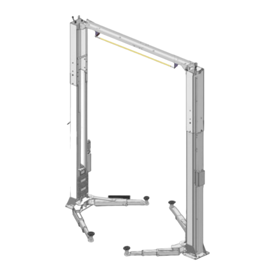
I. PRODUCT FEATURES AND SPECIFICATIONS CLEAR-FLOOR DIRECT-DRIVED MODEL FEATURES Model OH-9(H) , OH-10(H) (See Fig. 1) · Direct-drived design, minimize the lift spare parts and breakdown ratio · Dual hydraulic cylinders, designed and made as standards, utilizing oil seal in cylinder ·... - Page 4 Arm Swings View For Model OH-9 Fig.2 Attention! Please make sure to place the arms in correct position before car drive in! Car in Fig.3...
- Page 5 Swing and extending the arms to the lifting point of vehicle Fig.4...
-
Page 6: Installation Requirement
II. INSTALLATION REQUIREMENT A. TOOLS REQUIRED Rotary Hammer Drill (Φ19) Carpenter’s ink marker Hammer Screw Sets Level Bar Tape Measure (7.5m) English Spanner (12") Pliers Ratchet Spanner with Socket (28 Socket Head Wrench (3 ... - Page 7 B. Equipment storage and installation requirements. The equipment should be stored or installed in a shady, normal temperature, ventilated and dry place. C. The equipment should be unload and transfer by forklift. Fig.6 D. SPECIFICATIONS OF CONCRETE (See Fig. 7) Specifications of concrete must be adhered to the specification as following.
-
Page 8: Steps Of Installation
III. STEPS OF INSTALLATION A. Location of Installation Check and insure the installation location (concrete, layout, space size etc.) is suitable for lift installation. B. Use a carpenter’s ink marker line to establish installation layout of base-plate (See Fig.8). Click a line 135”... - Page 9 5. Open the bag 1 of parts and check the parts according to parts box list (See Fig. 13). Fig. 13 6. Open the bag 2 of parts and check the parts according to parts bag list (See Fig. 14). OH-9/OH-9H OH-10/OH-10H Fig. 14...
- Page 10 This lift is designed with 2-Section columns. Adjust the height according to the ceiling height and connect the inner and extension columns. OH-9, : Not suitable for installation when the height of the workshop is less than 143-3/4"; only low setting installation for height between 143-3/4" - 151-1/2 "; the height of the workshop is greater than 151-1/2", installation can be in both high and...
- Page 11 1. High setting installation, choose the low holes of the outer column and install with the inner column. High setting Fig.16 2. Low setting installation, choose the high position holes of the outer column and install with the inner column. (See Fig.17). Low setting Fig.17...
- Page 12 F. Position columns (See Fig. 18) Position the columns on the installation layout of base-plate, Install the anchor bolts. Check the Columns plumpness with level bar, and adjusting with the shims if the columns are not vertical. Do not tighten the Anchor Bolts. Width between Columns: 112-1/4”...
- Page 13 G. Install overhead top beam 1. The hook on the top coupling assembly is hung on the outer column to lock the screws, and then the top beam is installed (See Fig. 19) Fig. 19...
- Page 14 2. Install the top beam, fix the anchor bolts. Tighten the anchor bolts with ratchet spanner with socket Note: Torque of Anchors is 150N.m Fig.20...
- Page 15 H. Install the limit switch control bar and limit switch (See Fig. 21). → Power-side Fix the control bar support bracket with Hex bolt M10*20,self-locking nut → Off-side and washer Control bar support bracket Installing Control bar socket bolt Fix socket (M10*40mm) Connecting bolt(M10*25m...
- Page 16 2. Tighten limit switch. Fix the limit switch on control bar support bracket of the power-side as the photo. The wire pass through the top beam and connected to the AC contactor of power unit. Limit switch Fig.23 I. Install safety device (See Fig. 24 & Fig. 25). Power-side safety device Fig.24 10 75A...
- Page 17 J. Install cables. Lift the carriages up by hand and make them be locked at the same level 1. Low setting cable connection .(See Fig.26) Cable install inside the column. Low Setting installation holes Cable 2 Cable 1 Cable 2 Fig.26...
- Page 18 2.High setting cable connection 2.1. Cable cross over from the bottom of the carriages and be pulled out from the open of carriages, then screw the two cable nuts (See Fig. 27). High Setting installation holes Screw the two cable nuts Cable Connecting direction...
- Page 19 2.2 Connecting cable for high setting (See Fig. 28). Cable 2 Cable 1 Cable 2 Fig. 28...
- Page 20 K. Install oil hose. 1. Oil-line connecting drawing. (See Fig.29) Fig.29...
- Page 21 2. Follow these step to connect the oil hose of power unit. Left oil outlet port Right oil outlet port Hex plug B. Assemble 90 fitting of power unit, and A. Disassemble the hex plug. connecting the oil hose. Plastic red plug D.
- Page 22 L.Install protective cover. (Fig.31) Tighten the M6*30 cup head bolt 1. Screw on cup head bolt M6*40 a little. 2. Install protective cover, then tighten the cup head bolt Only for high setting Fig.32...
- Page 23 M. Install safety cable (See Fig. 33) Safety cable go out of gap Safety cable across pulley bracket Wire of limited switch Oil hose Safety cable connect to power-side safety device finally. Safety cable first connect to off-side safety device Fig.33...
- Page 24 Note: Don’t cross the oil hose and safety cable together (See Fig. & Fig. 35). Tie the hose and cable with a tape Safety Cable Oil Hose Wire Cable Power-side Safety Device Offside Safety Device Fig. Fig. N. Cable limited block Installation. Fig.36 O.
- Page 25 Loosen the Bolt Snap Ring Fig. Fig. Use the 8 Socket Head Wrench to loosen the Socket Bolt. 3. Adjust the arm lock as direction of arrow (See Fig. 39) Locking the bolts Adjust the arm lock Fig. 39 Fig. Adjusting moon gear and Locking the bolts after the moon arm lock to mesh.
- Page 26 2. Pay attention to the direction of rotations when using three phase motors. Single phase motor wiring (See Fig. 41) a. When power supply wires are active wire L and neutral wire N ,connecting active wire L to terminals of AC contactor marked L1, connecting neutral wire N to terminals of AC contractor marked L3.
-
Page 27: Exploded View
IV. EXPLODED VIEW OH-9 Fig. 44... - Page 28 PARTS LIST OH-9 Item Part No. Description 10206019 Snap Ring φ19 10209012 Elastic latch φ3.2 10209128 Washer φ20 10209057A Bronzed bush for Pulley Ф*25.4*Ф19.1*14.5 11206020 Pulley 11206202 Power-side Inner Column 10209003 Hex Bolt M8*25 10209004 Rubber Ring φ8*20*3 10209005 Self-locking Nut M8 11217436 Safety device spacer φ27*15...
- Page 29 OH-9 Item Part No. Description 11206191 Toe guard bar 10209019 Screw M6*16 10209018 Protective Rubber 11279004 Carriage Front right Arm 10279010 Front left Arm 10279009 Rubber pad assy. 10201046A 10420138 Socket bolt M6*16 10209134 Rubber pad 11680030C Rubber pad bracket 10209034 Lock Washer φ8...
- Page 30 OH-9 Item Part No. Description 10203778 Protective Cover L=1545 10206079 Cap Head Bolt M6*40 11206203 Offside Inner column Stackable Adapter (1.5”) 11209051B 11209052B Stackable Adapter (2.5”) 11209053B Stackable Adapter (5”) 10217066 Hex Bolt M6*15 10209149 Lock Washer φ6 10420045 Washer φ6 10206064A Cable φ9.52*10048mm...
- Page 31 4.1 Rear arm assy. (10279011) explosive view Fig.45 QTY. Item Part No. Description 10206048 Hex nut M10*30 10209039 Washer φ10 10209022 Washer φ10 11206049 Moon gear 11206192 Rear outer arm 10201149 Cap head bolt M8*12 11206193 Rear inner arm 4.2 Front left arm assy. (10279009) explosive view Fig.46 Item Part No.
- Page 32 4.3 Front right arm assy. (10279010) explosive view Fig.47 Item Part No. Description QTY. 10206048 Hex nut M10*30 10209039 Lock Washer φ10 10209022 Washer φ10 11206049 Moon gear 11279006 Outer arm - Front right 11206189 Middle arm - Front 10201149 Cap head bolt M8*12 11201049A Inner arm - Front...
- Page 33 Part list for cylinder Item Part No. Description QTY. 30-1 10209069 O-ring 30-2 10209070 Bleeding Plug 30-3 10209071 Support Ring 30-4 10209072 Y-ring OSI 30-5 10209073 O-ring 30-6 11209074 Piston 30-7 10209075 O-Ring 30-8 11217076 Piston rod 30-9 11209077 Piston Rod Fitting 30-10 10209078 Dust ring...
- Page 34 Part list of power unit (220V/60HZ/single phase) Item Part No. Description QTY. Item Part No. Description QTY. AC contractor Rubber pad 81400180 41030055 Starting capacitor Motor wiring cover 81400250 81400287 Running capacitor AMGO label 81400200 71111104 Screw with washer Throttle valve 10420148 81400560 Capacitor cover...
-
Page 35: Test Run
V. TEST RUN 1. Adjustment of synchronous cable (See Fig. 51) Use wrench to hold the cable fitting, meanwhile using ratchet spanner to tighten the cable nut until the two cables are in the same tension. If the two vehicle carriages do not Synchronized Cable nut when lifting and lowering, please screw and tighten the cable nut on the lower side carriage. -
Page 36: Operation Instruction
5. Test with load After finishing the above adjustment, test running the lift with load. Run the lift in low position for several times firstly, make sure the lift can rise and lower synchronously, the Safety Device can lock and release synchronously. And then test run the lift to the top completely. -
Page 37: Maintenance
To lower vehicle 1. Be sure clear of around and under the lift, only leaving operator in lift area; 2. Push button UP to raise the vehicle slightly, and then release the safety device, lower vehicle by pushing release handle. 3. -
Page 38: Trouble Shooting
VIII.TROUBLE SHOOTING TROUBLE CAUSE REMEDY 1. Button does not work 1. Replace button 2. Wiring connections are not in good 2.Repair all wiring connections condition Motor does not 3. Motor burned out 3. Repair or replace motor 4. Height Limit Switch is damaged 4. - Page 39 AMGO HYDRAULIC CORPORATION 1931 Joe Rogers Blvd, Manning, South Carolina, Zip: 29102 Tel: (803) 505-6410 Manual No.:72228005 Fax: (803) 505-6410 Revised date:2022/07...
Need help?
Do you have a question about the OH-9 and is the answer not in the manual?
Questions and answers