Table of Contents
Advertisement
Quick Links
Model No. EE-HDM8 series
Installation, Operation
Mobile Columns
and Parts Manual
Wireless Technology
Capacity: 8000 kg each column
Translated Version
A maximum combination of 48 columns
Distributed by
DATE: 23/11/2023
Please read this entire manual carefully and completely before installation or operation of the lift.
Advertisement
Table of Contents

Related Manuals for EAE EE-HDM8 Series


Summary of Contents for EAE EE-HDM8 Series
- Page 1 Model No. EE-HDM8 series Installation, Operation Mobile Columns and Parts Manual Wireless Technology Capacity: 8000 kg each column Translated Version A maximum combination of 48 columns Distributed by DATE: 23/11/2023 Please read this entire manual carefully and completely before installation or operation of the lift.
-
Page 2: Important Notes
Liability The liability of EAE is limit to the amount that the customer has actually paid for this product. This exclusion of liability does not apply to damages caused through willful misconduct or gross negligence on the part of EAE All information in this manual is believed to be correct at time of publication. -
Page 3: Table Of Contents
Installation, Operation and Parts Manual EE-HDM8 series IMPORTANT NOTES ..............................2 IMPORTANT INFORMATION FOR SAFE USE ......................4 1.1 Warning labels ..............................4 1.2 Qualified operators .............................. 4 1.3 Floor and space conditions ..........................4 1.4 Good condition of the lifting system ........................5 1.5 Correct manner .............................. -
Page 4: Important Information For Safe Use
Installation, Operation and Parts Manual EE-HDM8 series Annex 2, Hydraulic schemes and parts list ......................25 Annex 3, Mechanical drawings and parts list ......................28 IMPORTANT INFORMATION FOR SAFE USE 1.1 Warning labels All safety warning labels are clearly depicted on the lift to ensure that the operator is aware of and avoid the dangers of using the lift in an incorrect manner. -
Page 5: Good Condition Of The Lifting System
Installation, Operation and Parts Manual EE-HDM8 series 1.4 Good condition of the lifting system - Run the lifting system without load for a complete cycle to ensure it is in good condition before loading. - Read the battery meter and ensure the battery is enough charged before using. -
Page 6: Descriptions Of The Lifting System
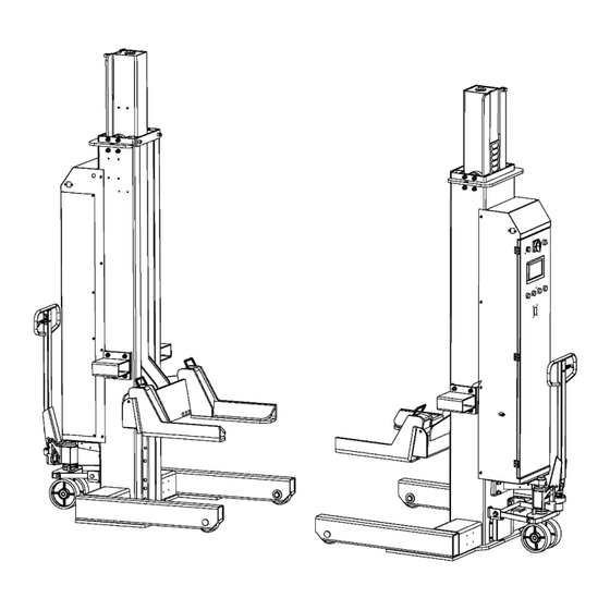
Installation, Operation and Parts Manual EE-HDM8 series DESCRIPTIONS OF THE LIFTING SYSTEM 2.1 General descriptions It is wheel supporting mobile column vehicle lift. Each column has a maximum lifting capacity of 8,000kg. A maximum combination of 48 columns work steadily in a group. It is an ideal lifting solution to heavy duty vehicles such as container trucks, coaches and army trucks. -
Page 7: Dimensions
Installation, Operation and Parts Manual EE-HDM8 series 2.3 Dimensions 2.4 Mechanical safety devices POS. Safety device Function Keep the carriage running Guiding roller wheel vertically under load. Keep the lifting system from Mechanical safety catch collapse in case of a hydraulic failure. -
Page 8: Specifications
Installation, Operation and Parts Manual EE-HDM8 series 2.5 Specifications Capacity 8000kg for each single column Charger 100-240VAC,4.5A, 50/60HZ Pressure relief valve 14MPa Electrical power DC24V 2.2 kW Power supply for the charger AC110~240V-1Ph (UP on the voltage requirement ) Operating voltage... -
Page 9: Unpacking And Handling
Installation, Operation and Parts Manual EE-HDM8 series UNPACKING AND HANDLING Each lifting column is reserved with two specialized steel tubes for transporting by a forklift. The steel tubes are attached at both sides of the column marked with the following warning label. -
Page 10: Use The Pallet Jack
Installation, Operation and Parts Manual EE-HDM8 series 4.3 Use the pallet jack The pallet jack is used to move the column by lifting it off the floor. Always descend the column onto the floor before raising. The pallet jack is operated by a hand grip and a lever inside the grip. -
Page 11: Get Familiar With The Control Panel
Installation, Operation and Parts Manual EE-HDM8 series 4.5 Get familiar with the control panel 4.5.1 Layout of the control panel Code Description Function Power indicator Display power status. Power switch Turn on or turn off the control power. Alarm buzzer Audible warning for desynchronization. - Page 12 Installation, Operation and Parts Manual EE-HDM8 series ICON Descriptions Indication of the total column quantity in a lifting group. For the operative column it displays in Green. For the rest non-operative columns, it displays in Red. ID: Identity code for a lifting group. It differs in different lifting groups.
-
Page 13: Set Up The Control System
Installation, Operation and Parts Manual EE-HDM8 series 4.5 Set up the control system using the HMI screen The columns with a same serial number on the marking plates have already been set up as a group before delivery. Turn on the power switch at each column respectively and all the columns will interconnect automatically GROUP MODE In this mode, all columns are interconnected and operated simultaneously. - Page 14 Installation, Operation and Parts Manual EE-HDM8 series BUILD A NEW NETWORK In case there needs to add or remove columns from the existed lifting group, it is necessary to rebuild a new network. Click the network icon on the Menu Page and access the page for building a network.
-
Page 15: Commissioning
Installation, Operation and Parts Manual EE-HDM8 series COMMISSIONING 5.1 Correct manners in use After the lifting system are correctly set up, get familiar with lift controls by running the lift through a few cycles before loading vehicle. Never raise just one end, one corner or one side of vehicle. The lifting system must be only used in a static position for lifting and lowering vehicles. - Page 16 Installation, Operation and Parts Manual EE-HDM8 series CAUTION: Check the status of the fork before push it under the wheels. All forks must be engaged before loading. The two locking positions of the fork must be symmetric to the central axis of the columns Raising ①...
-
Page 17: Fix The Breakdown Caused By Desynchronization
Installation, Operation and Parts Manual EE-HDM8 series 5.3 Fix the breakdown caused by desynchronization Desynchronization within the limited value can be automatically calibrated by the lifting system itself. In case desynchronization exceeds the limited value that had been set up, a warning tip will occur on the screen of the column which has the least rising height among the four columns. -
Page 18: Trouble Shooting
Installation, Operation and Parts Manual EE-HDM8 series TROUBLE SHOOTING TROUBLES POSSIBLE CAUSES SOLUTIONS Poor contact of the button for raising. Check with a voltage meter. Replace the button. No battery power. Check and charge the battery. Insufficient oil level in the tank. -
Page 19: Maintenance
Installation, Operation and Parts Manual EE-HDM8 series TROUBLES POSSIBLE CAUSES SOLUTIONS Different lifting The lifting system has not been set up Set up the lifting system according to the instructions given in heights correctly. section 4.5 in the users' manual. - Page 20 Installation, Operation and Parts Manual EE-HDM8 series POS. Components Inspection method Period Picture Inspect each latching position. No obvious deformation is allowed. Locking device of the fork Every day See the above scheme Stop using the lift if any deformation is found.
- Page 21 Installation, Operation and Parts Manual EE-HDM8 series POS. Components Inspection method Period Picture condition that the full capability of lifting cycles is less than 5. Take the valves off and check if any solid substance attached. Tidy and Valves assembled on the...
-
Page 22: Annex 1, Electrical Schemes And Parts List
Installation, Operation and Parts Manual EE-HDM8 series Annex 1, Electrical schemes and parts list... - Page 23 Installation, Operation and Parts Manual EE-HDM8 series...
- Page 24 Installation, Operation and Parts Manual EE-HDM8 series D-Code P-code Component Name Specification 321301027 Circuit board WL-433 321004136 Rope displacement sensor WF60-2500-0015F24-00203 321203171 Battery 329*172*215mm 12V100AH(12V106AH) 320304001 Power switch LW26GS-20-04 320505029 Wire terminals MBKKB2.5 SB1,SB2,SB3 320401041 Push button NP2-EA15(CDLA6H-EA15) 320301011 Limit switch...
- Page 25 Installation, Operation and Parts Manual EE-HDM8 series Annex 2, Hydraulic schemes and parts list...
- Page 26 Installation, Operation and Parts Manual EE-HDM8 series Pos. Code Component Name Description 320204275 DC motor DM42-2AWU-3BA2R,24VDC,2.2KW 330503030 Stainless hoop 105-127*12/JB/T8870,1 320402019 Motor starter 684-24C1-212-17,24VDC 330304010 Relief valve DANRV-08-50 310101010 Hex socket threaded fitting G1/4---G1/4 207103025 Composite washer 13_7X20X1_5 330105043 Hydraulic block...
- Page 27 Installation, Operation and Parts Manual EE-HDM8 series POS. Code Component Name Specification 622034392 Power unit DC24V-2.2KW-F2.5-DC24 310101008 Connector M14*1.5-G1/4 inside cone Φ8*2,L=890 624008188 Rubber oil hose 310101010 Straight connector G1/4---G1/4 inside cone 615068005 Cylinder YG90108-60-1700...
- Page 28 Installation, Operation and Parts Manual EE-HDM8 series Annex 3, Mechanical drawings and parts list POS. Code Component Name Specification 202109085 Hex socket cylinder head screw M12X30-GB70_1 410901144 Connection plate HDM104-A5 204301009 Circlip 410220630 Circlip...
- Page 29 Installation, Operation and Parts Manual EE-HDM8 series POS. Code Component Name Specification 205201010 Cylinder needle bearing NUP2206E 420680057 Upside pulley HDM84-A14-B2 410901148 Big washer 6254E-A1-B2 614901011 Upside pulley Shaft HDM104-A13-B1 204101007 Flat washer 204201006 Spring washer 202109085 Hex socket cylinder head screw...
- Page 30 Installation, Operation and Parts Manual EE-HDM8 series POS. Code Component Name Specification 410220630 Internal Circlip 204301011 Shaft Circlip 202111013 Hex socket flat head screw M12X16-GB70_3 614901010 Power unit holder HDM84-A9 614901009 Battery holder HDM84-A8 202109017 Hex socket cylinder head screw...
Need help?
Do you have a question about the EE-HDM8 Series and is the answer not in the manual?
Questions and answers