Table of Contents
Advertisement
Quick Links
Advertisement
Table of Contents

Related Manuals for EAE EE-6435B.WF


Summary of Contents for EAE EE-6435B.WF
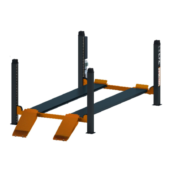
- Page 1 EE-6435B.WF Installation, Operation Four Post Lift and Parts Manual Electrical Release With secondary lift for wheel free service Lifting capacity: 4000KG/5000KG Distributed by Please read this entire manual carefully and completely before installation or operation of the lift. 26/07/2016...
-
Page 2: Table Of Contents
Installation, Operation and Parts Manual EE-6435B.WF SAFETY NOTES ............................4 1.1 Operation of lifting platforms ........................4 1.2 Checking of the lifting platforms ......................... 4 1.3 Important safety notices ..........................5 1.4 Safety advices ............................... 6 1.5 Risks and safety instructions ........................7 1.6 Noise level .............................. - Page 3 Liability The liability of EAE is limit to the amount that the customer has actually paid for this product. This exclusion of liability does not apply to damages caused through willful misconduct or gross negligence on the part of EAE.
-
Page 4: Safety Notes
Installation, Operation and Parts Manual EE-6435B.WF SAFETY NOTES 1.1 Operation of lifting platforms This lift is specially designed for lifting motor vehicles. Users are not allowed to use it for any other purposes. The applicable national regulations, laws and directives must be observed. -
Page 5: Important Safety Notices
Installation, Operation and Parts Manual EE-6435B.WF 1.3 Important safety notices 1.3.1 Do not install the lift on any asphalt surface. 1.3.2 Read and understand all safety warnings before operating the lift. 1.3.3 Do not leave the controls while the lift is still in motion. -
Page 6: Safety Advices
Installation, Operation and Parts Manual EE-6435B.WF 1.4 Safety advices All safety warning labels are clearly depicted on the lift to ensure that the operator is aware of and avoid the dangers of using the lift in an incorrect manner. The labels must be kept clean and they have to be replaced if detached or damaged. -
Page 7: Risks And Safety Instructions
Installation, Operation and Parts Manual EE-6435B.WF 1.5 Risks and safety instructions During lift functioning, the operator must remain in the control station as defined in figure 1. The presence of persons beneath the cross-pieces and/or the platforms when they are moving, or the presence of persons inside the danger zone indicated in figure 2 is strictly prohibited. - Page 8 Installation, Operation and Parts Manual EE-6435B.WF RISK OF CRUSHING (PERSONNEL) When the platforms and the vehicle are lowering personnel are prohibited from entering the area beneath the movable parts of the lift (Fig.4). The lift operator must not start the lift until it has been clearly established that there are no persons in danger zone (Fig 1, 4, 5) (Fig.
-
Page 9: Noise Level
Installation, Operation and Parts Manual EE-6435B.WF RISK OF SLACKENING OF LIFT CABLES Caused by objects left leaning against the posts or on the platforms. (Fig. 9) (Fig.8) risk of vehicle falling (Fig.9) risk of slackening of lift cables. RISK OF SLIPPING Caused by lubricant contamination of the floor around the lift (Fig. -
Page 10: Packing, Storage And Transportation
Installation, Operation and Parts Manual EE-6435B.WF PACKING, STORAGE AND TRANSPORTATION Packing, lifting, handling, transporting operations must be performed only by experienced personnel with appropriate knowledge of the lift and after reading this manual. 2.1 The lift was dismantled into the following2 parts for transportation... -
Page 11: Products Descriptions
Installation, Operation and Parts Manual EE-6435B.WF stable. Once the stack is complete, restrain it using straps, ropes or other suitable methods. A maximum of two packs can be stacked on lorries, in containers, and in railway wagons, on condition that the packs are strapped together and restrained to stop them falling. -
Page 12: Dimensions
Installation, Operation and Parts Manual EE-6435B.WF 3.3 Dimensions MODEL DATA 6435BWF.48L 6435BWF.52L 6435BWF.57L 4880 5280 5780 5970 6370 6870 4888 5288 5788 4438 4838 5338 1580 1980 2280 1270... -
Page 13: Safety Devices Descriptions
Installation, Operation and Parts Manual EE-6435B.WF 3.4 Safety devices descriptions Safety Device Function Safety rod Ensure mechanical safety in the rising and lowering process and lock the Safety block A lifting platform at expected height. Safety block B Electromagnet Release the safety lock. -
Page 14: Technical Data
Installation, Operation and Parts Manual EE-6435B.WF 3.5 Technical data Item Data Power Form Electro-hydraulic Rated capacity of the lifting platform 4000KG(48L/52L), 5000KG(48L/52L/57L) Full rise height of the main lift 1850mm Initial height of the main lift 225mm Full rise time of the main lift ≤70S... -
Page 15: Installation Instructions
Installation, Operation and Parts Manual EE-6435B.WF INSTALLATION INSTRUCTIONS 4.1 Preparations before installation 4.1.1 Space requirements. Refer to 3.3 for the dimensions of the lift. There must also be a clearance of at least 1 meter between the lifting platform and fixed elements (e.g. - Page 16 Installation, Operation and Parts Manual EE-6435B.WF 4.1.3 Foundations preparations C20/25 concrete base with strength more than 3000psi, tolerance of flatness less than 5mm and minimum thickness of 200mm. In addition, newly built concrete ground must be older than 20days. If not specially noted, this lift is for indoor use only.
- Page 17 Installation, Operation and Parts Manual EE-6435B.WF 4.1.4 Tools and equipment needed for installation Tool name Specification Quantity needed Electrical drill With D16 and D18 drill bit. Open spanner D17-19mm Adjustable spanner bigger than D30mm Cross socket screw driver Quick spanner handle adapter/ Ratchet...
-
Page 18: Installation Attentions
Installation, Operation and Parts Manual EE-6435B.WF Name Flat washer Ф8 Ramp shaft Expansion bolt Control cabinet Power unit Manual Drive-on ramp 4.2 Installation attentions 4.2.1 Joints of oil hose and wiring must be firmly connected in order to avoid leakage of oil hose and looseness of electrical wires. - Page 19 Installation, Operation and Parts Manual EE-6435B.WF Step 3: Use the forklift to have the general parts properly positioned. For convenient installation, it would be better to pad something supporting under the platform. Oil cylinder, steel cable and oil hose have already been fixed in the power side platform (platform with oil cylinder beneath) before packing.
- Page 20 Installation, Operation and Parts Manual EE-6435B.WF 3. Pull out the steel cables from both ends of the cross beam and fasten them on the top plate of post (please see the Annex for the steel cable connection) Step 6: Fit on 8 nylon sliders and 4 protection covers 1.
- Page 21 Installation, Operation and Parts Manual EE-6435B.WF Step 11: Leveling Attention: No vehicle on platforms when leveling. Firstly, level the platforms when mechanical safety locks are disengaged. Switch on and press the UP button when the green power indicating light is on. When the steel cable has been tightened, measure if the two platforms are of the same height from the ground with a leveling pipe.
- Page 22 Installation, Operation and Parts Manual EE-6435B.WF Step 12: Adjust cable slack protection limit switches. Make the platform be locked at height of 800mm and adjust the limit switch as showed in the following drawing with hex socket spanner (3mm) Step 13: Fix the expansion bolts Refer to 3.3 and adjust the distance between posts before drilling holes for expansion bolts.
-
Page 23: Items To Be Checked After Installation
Installation, Operation and Parts Manual EE-6435B.WF 4.4. Items to be checked after installation Check items Are the posts vertical to the floor? Are the oil hoses well connected? Are the steel cables well connected? Are two platforms well connected? Are electrical connections right? -
Page 24: Descriptions Of Control Panel
Installation, Operation and Parts Manual EE-6435B.WF 5.2 Descriptions of control panel POS. Name Function Alarm buzzer Low height warning Power switch Power on/ off Power indicator Display if electricity is connected UP button Control the rising movement DOWN I button Control the initial lowering movement 1.1 In case the clearance between the platform and the floor is more than... -
Page 25: Flow Chart For Operation
Installation, Operation and Parts Manual EE-6435B.WF 5.3 Flow chart for operation 5.4 Operation instructions 5.4.1 Use the main lifting platform Turn the selection switch to the state of “LIFT” Raise the lift 1. Turn on the power switch. 2. Park the vehicle on the platforms to ensure its gravity is positioned midway of the platforms. -
Page 26: Emergency Lowering In Case Of No Power
Installation, Operation and Parts Manual EE-6435B.WF Lower the Secondary lift Attention: in case the platform extensions of the auxiliary lift are used, the operator needs to release the extension after the four wheels of vehicle lay on the main platforms. -
Page 27: Trouble Shooting
Installation, Operation and Parts Manual EE-6435B.WF TROUBLE SHOOTING ATTENTION: If the trouble could not be fixed by yourself, please do not hesitate to contact us for help .We will offer our service at the earliest time we can. By the way, your troubles will be judged and solved much faster if you could provide us more details or pictures of the trouble. -
Page 28: Maintenance
Installation, Operation and Parts Manual EE-6435B.WF MAINTENANCE Easy and low cost routine maintenance can ensure the lift work normally and safely. Following are requirements for routine maintenance. You may decide the frequency of routine maintenance by consulting your lift’s working conditions and time. -
Page 29: Annex
Installation, Operation and Parts Manual EE-6435B.WF ANNEX Annex1, Steel cable connection... -
Page 30: Annex2, Hydraulic Schemes And Parts List
Installation, Operation and Parts Manual EE-6435B.WF Annex2, Hydraulic schemes and parts list Oil tank Oil tank cover Motor Coupling Gear pump Over-flow valve Singe way valve Solenoid unloading valve Press supplementing valve Three way directional valve Hydraulic block Three way valve... - Page 31 Installation, Operation and Parts Manual EE-6435B.WF Pos. CODE Name Specification Motor 320201004- Motor 380V-2.2KW AL -3PH-50HZ-2P2.2KW 624001207 Rubber oil hose ø8,L=6250 624001* PU hose ø8,L=6750 624001242 Rubber oil hose 410277110 T shape three way hydraulic block 64040-HB1-A01-B01 310102001 Right angle connector...
- Page 32 Installation, Operation and Parts Manual EE-6435B.WF Pos. CODE Name Specification 201103001 Hex flange screw M5*25 202109064 Hex socket cylinder head screw M6*30 207103019 Composite seal ring 310101003 Straight connector M14X1.5-G1/4/60 310102013 90 degree connector with swivel 08N-M14S 330101079 Composite hydraulic block...
-
Page 33: Annex3, Electrical Schemes And Parts List
Installation, Operation and Parts Manual EE-6435B.WF Annex3, Electrical schemes and parts list... - Page 34 Installation, Operation and Parts Manual EE-6435B.WF...
- Page 35 Installation, Operation and Parts Manual EE-6435B.WF POS. Code Name Specification 320101075 Transformer JBK3-400VA 400V-24V SQ1,SQ2,SQ7 320301009 Limit switch 8104 TZ-8104 SQ3-SQ6 320301011 Limit switch 8108 TZ8108 320303010 Option Switch (binary) AR22PR-222B 320304001 Power switch LW26GS-20/04 320401017 Button AR22F0R-20-W...
- Page 36 Installation, Operation and Parts Manual EE-6435B.WF POS. Code Name Specification 320402002 Emergency stop XB2BS542C 320601001 Relay HH54P-L/DC24V(MY4NJ) 320601007 Relay HH64P-L/DC24V-10A(LY4NJ) 320601010 Relay holder PTF-14A-E 320601011 Relay holder PYF-14A-E 320601018 Relay fixer 320602001 Time relay ST6P-2AC24V,5S 320602006 Time relay holder PYF-08A-E...
-
Page 37: Annex4, Exploded Drawings And Parts List
Installation, Operation and Parts Manual EE-6435B.WF Annex4,Exploded drawings and parts list Pos. CODE Name NOTE Power side post B Secondary post Power side crossbeam Secondary crossbeam Main platform Secondary platform Slip plate Front wheel retaining plate 614027279 Portable box(380) 614027280... - Page 38 Installation, Operation and Parts Manual EE-6435B.WF Pos. CODE Name NOTE 208101001 Steel rope clip 615027038B Steel rope 615027037B Steel rope 615027036 Steel rope Pos. CODE Name NOTE 614027701 Main post 614027091B Secondary post...
- Page 39 Installation, Operation and Parts Manual EE-6435B.WF Pos. CODE Name NOTE 612027001B Safety rod 420270140 Clip of safety rod 420270090 Post cap 614027107 Control unit holder Control unit Power unit 420250050B Round hose protector 615027038B Steel rope 615027037B Steel rope 615027036...
- Page 40 Installation, Operation and Parts Manual EE-6435B.WF Pos. CODE Name NOTE 614027623 Main crossbeam 614027624 Secondary crossbeam 410274120 Pulley A 205101070 Lubrication bearing 40*50*40 612027002 Safety block A 410270020 Slider 420270050 Spacer A 420270060 Spacer B 410270021 Pulley shaft A 208106001...
- Page 41 Installation, Operation and Parts Manual EE-6435B.WF Pos. CODE Name NOTE 410270051D Safety block B1 410270061 Adjustable rod A 410270660 Spring 330310007 Electromagnet 410270601 Adjustable post 410270151 Adjustable chip 410270011 Slider holder 420270010 Slider 612027004 Safety block A2 410270121D Safety block B2...
- Page 42 Installation, Operation and Parts Manual EE-6435B.WF Pos. CODE Name NOTE 614027571 Platform A .57L.50T 57L.50T 614027573 Platform A .52L.50T 52L.51T 614027575 Platform A .48L.50T 48L.52T 614027577 Platform A .48L.40T 52L.40T 614027579 Platform A .48L.40T 48L.40T 614027572 Platform B .57L.50T 57L.50T 614027574 Platform B .52L.50T...
- Page 43 Installation, Operation and Parts Manual EE-6435B.WF Pos. CODE Name NOTE 208106001 Straight pressed oil cup 202109060 Hex socket button head screw M12*145 GB/T 70 615027005 5T oil cylinder 614027033B Steel rope connection block 208010001 Steel rope clip Open slotted nut...
- Page 44 Installation, Operation and Parts Manual EE-6435B.WF Pos. CODE Name NOTE 320301009 Limit switch 8104 Hydraulic block Pos. CODE Name NOTE 614027268B Outer connection rod A of the secondary lift 614027269B Outer connection rod B of the secondary lift 614027270B Inner connection rod A of the secondary lift...
- Page 45 Installation, Operation and Parts Manual EE-6435B.WF Pos. CODE Name NOTE 205101024 Bearing 3055 203103018 Locking nut 204101012 Flat washer 204301011 Type B circlip M 30 204301009 Circlip φ25 202109080 Hex socket cylinder head screw 204101006 Flat washer φ10 204201005 Spring washer φ10...
Need help?
Do you have a question about the EE-6435B.WF and is the answer not in the manual?
Questions and answers