Table of Contents
Advertisement
Quick Links
Advertisement
Table of Contents

Subscribe to Our Youtube Channel
Related Manuals for EAE EE-62CE-60T


Summary of Contents for EAE EE-62CE-60T
- Page 1 Model No. EE-62CE-60T Installation, Operation Two Post Vehicle Lift and Parts Manual Chassis Supporting Electrical Release Lifting Capacity 6000KG Distributed by Please read this entire manual carefully and completely before installation or operation of the lift. DATE:28/02/2023...
-
Page 2: Important Notes
Liability The liability of EAE is limit to the amount that the customer has actually paid for this product. This exclusion of liability does not apply to damages caused through willful misconduct or gross negligence on the part of EAE. -
Page 3: Table Of Contents
Installation, Operation and Parts Manual EE-62CE-60T IMPORTANT NOTES ............................2 SAFETY NOTES ..............................4 1.1 Operation of lifting platforms ..........................4 1.2 Checking of the lifting platforms..........................4 1.3 Important safety notices ............................5 1.4 Warning labels ............................... 6 1.5 Potential safety risks .............................. 7 1.6 Noise level ................................ -
Page 4: Safety Notes
Installation, Operation and Parts Manual EE-62CE-60T SAFETY NOTES 1.1 Operation of lifting platforms This lift is specially designed for lifting motor vehicles. Users are not allowed to use it for any other purposes. The applicable national regulations, laws and directives must be observed. -
Page 5: Important Safety Notices
Installation, Operation and Parts Manual EE-62CE-60T rules of engineering to be able to check and give an expert option on lifting platforms. 1.3 Important safety notices 1.3.1 Recommend for indoor use only. DO not expose the lift to rain, snow or excessive moisture. -
Page 6: Warning Labels
Installation, Operation and Parts Manual EE-62CE-60T 1.4 Warning labels All safety warning labels are clearly depicted on the lift to ensure that the operator is aware of and avoid the dangers of using the lift in an incorrect manner. The labels must be kept clean and they have to be replaced if detached or damaged. Please read carefully the... -
Page 7: Potential Safety Risks
Installation, Operation and Parts Manual EE-62CE-60T 1.5 Potential safety risks 1.5.1 Main voltage nsulation damage and other faults may result in accessible components being live Safety measures: Only ever use the power cord provided or a tested power cord. -
Page 8: Packing, Storage And Transportation
Installation, Operation and Parts Manual EE-62CE-60T PACKING, STORAGE AND TRANSPORTATION Packing, lifting, handling, transporting operations must be performed only by experienced personnel with appropriate knowledge of the lift and after reading this manual. Packing, lifting, handling, transporting operations must be performed only by experienced personnel with appropriate knowledge of the lift and after reading this manual. -
Page 9: Products Descriptions
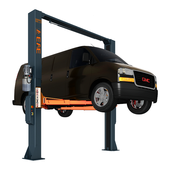
Installation, Operation and Parts Manual EE-62CE-60T PRODUCTS DESCRIPTIONS 3.1 General descriptions This chassis supporting vehicle lift for road vehicles. It is mainly composed by two posts, two carriages, four swing arms and a power and control unit. It is driven by an electro-hydraulic system. The gear pump delivers hydraulic oil to oil cylinders and pushes upwards its piston. The piston drives to raise the carriage and swing arms. -
Page 10: Dimensions
Installation, Operation and Parts Manual EE-62CE-60T 3.4 Dimensions Overall height: 4451... - Page 11 Installation, Operation and Parts Manual EE-62CE-60T Overall height: 5051...
-
Page 12: Safety Devices Descriptions
Installation, Operation and Parts Manual EE-62CE-60T 3.5 Safety devices descriptions POS. Descriptions Function Roof protective limit switch Stop rising in case vehicle roof has touched the overhead bar. Max height limit switch Stop rising at max height. Mechanical locking unit Catch the carriages in case of hydraulic failure. -
Page 13: Installation Instructions
Installation, Operation and Parts Manual EE-62CE-60T INSTALLATION INSTRUCTIONS 4.1 Preparations before installation 4.1.1 Space requirements. Refer to 3.4 for the dimensions of the lift. There must also be a clearance of at least 1 meter between the lifting platform and fixed elements (e.g. -
Page 14: General Installation Steps
Installation, Operation and Parts Manual EE-62CE-60T 4.3 General Installation Steps ONLY TRAINED AND QUALIFIED INSTALLERS CAN PERFORM LIFT INSTALLATION DUTIES. Step 1: Remove the packaging and take out the accessories attached. : Attention The packs must be opened adopting all the precautions required to avoid injury to persons (keep at a safe distance when cutting the straps) or damage to parts of the machine (be careful that no parts are dropped while you are opening the packing). - Page 15 Installation, Operation and Parts Manual EE-62CE-60T Step 5: Erect and secure the post. Screw Torque: 80-100N*m 1. Make the posts face to each other and the distance between the posts equals to the length of the overhead crossbeam. Use proper means to erect the post.
- Page 16 Installation, Operation and Parts Manual EE-62CE-60T Step 7: Connect the synchronization steel cables. 1. Route and fix according to the following diagram of steel cable connection. 2. Use suitable means to raise carriages at both sides to the first latching point. Ensure the both carriages are locked.
- Page 17 Installation, Operation and Parts Manual EE-62CE-60T 2. Connect oil hoses to the “T” connector in the power side post. Don’t let any solid substance go into the hydraulic line. Ensure the connectors are screwed tight against leakage. 1.Oil hose 2.Power unit 3.Oil hose...
- Page 18 Installation, Operation and Parts Manual EE-62CE-60T Step 10: Connect electrical system. Electrical connection must be done by qualified electricians. Check that the supply voltage is adapted to the voltage of the lift. Connect electrical wires referring to the following wire connection scheme.
- Page 19 Installation, Operation and Parts Manual EE-62CE-60T 3. Fix roof protection limit switch onto the overhead crossbeam and connect its wire to the corresponding terminals in the control box. 1. Limit switch 2. Cross socket cap head screw M4x25 3. Wire comes with the limit switch 4.
- Page 20 Installation, Operation and Parts Manual EE-62CE-60T 5. Connect wires come from motor and solenoid valve to the corresponding terminals in the control box. 1. control box 2. Solenoid valve wire 3.Motor wire 4.Main power cable to be connected with external electricity supply Step 11: Install lifting arms.
- Page 21 Installation, Operation and Parts Manual EE-62CE-60T Step 13: Trial running. Get familiar with lift controls by running the lift through a few cycles before loading vehicle on lift. This step is of particular importance for it can check if the oil hose is well connected. The connection is qualified when there is no abnormal sound or leakage after having been tested for 5-6 times.
-
Page 22: Items Be Checked After Installation
Installation, Operation and Parts Manual EE-62CE-60T 4.4 Items be checked after installation Check items Screw torque of expansion bolts : 80-100Nm; √ Rising speed ≥20mm/s; √ Noise with rated load ≤75dB(A); √ Grounding resistance: not bigger than 4Ω; √ Height difference of the two carriages ≤5mm;... -
Page 23: Operation Instructions
Installation, Operation and Parts Manual EE-62CE-60T 5.2 Operation instructions To avoid personal injury and/or property damage, permit only trained personnel to operate the lift. After reviewing these instructions, get familiar with lift controls by running the lift through a few cycles before loading vehicle on lift. Always lift the vehicle using all four adapters. -
Page 24: Trouble Shooting
Installation, Operation and Parts Manual EE-62CE-60T TROUBLE SHOOTING ATTENTION: If the trouble could not be fixed by yourself, please do not hesitate to contact us for help. We will offer our service at the earliest time we can. Troubles could be judged and solved much faster when more details or pictures could be provided. -
Page 25: Maintenance
Installation, Operation and Parts Manual EE-62CE-60T MAINTENANCE Following are requirements for routine maintenance. Easy and low cost routine maintenance can ensure the lift work normally and safely. Frequency of routine maintenance is determined by working condition and frequency. Components Methods... - Page 26 Installation, Operation and Parts Manual EE-62CE-60T Components Methods Period Inspect if the valve leaks or not. Clean or change the valve if it Unloading valve Every day leaks. Check the synchronization of both carriages and adjust the Steel cable Every day tightness of the cable if desynchronization is unacceptable.
-
Page 27: Annex 1, Floor Plan
Installation, Operation and Parts Manual EE-62CE-60T Annex 1, Floor plan Indoor installation only. There must also be a clearance of at least 1 meter between the lifting platform and fixed elements (e.g. wall) in all lifting positions. There must be sufficient space for driving vehicles on and off. -
Page 28: Annex 2, Electrical Schemes And Parts List
Installation, Operation and Parts Manual EE-62CE-60T Annex 2, Electrical schemes and parts list... - Page 29 Installation, Operation and Parts Manual EE-62CE-60T POS. Code Description 320104006 Transformer (380V400V415V-24V) 320102014 Transformer 400V230V-24V (dual voltage) 320801001 Circuit breaker C16/3P 320801003 Circuit breaker C25/3P (for dual voltage) 320803003 Circuit breaker 320803006 Circuit breaker 320901011 AC contactor 320301002 Limit switch...
- Page 30 Installation, Operation and Parts Manual EE-62CE-60T...
-
Page 31: Annex 3, Hydraulic Schemes And Parts List
Installation, Operation and Parts Manual EE-62CE-60T Annex 3, Hydraulic schemes and parts list 1.oil tank 2.filter 3.gear pump 4.coupling 5.motor 6.composite hydraulic block 7.cushion valve 8.overflow valve 9.single way valve 10.solenoidl unloading valve 11.flow control valve 12.oil tank cover 13.composite connector... - Page 32 Installation, Operation and Parts Manual EE-62CE-60T POS. Code Description Specification Power unit 2.2kW/3.0kW 207103019 Composite washer 310101008 Transfer connector M14*1.5-G1/4 inside cone 624002093 Oil hose L=360 615006003 Three way connector 6214E-A4-B4 624002094 Oil hose (for post with a total height of 4451)
- Page 33 Installation, Operation and Parts Manual EE-62CE-60T POS. Code Description Specification 330405030 Oil tank 330101063B Composite hydraulic block YF-2 330308006 Unloading solenoid valve DHF06-220H/DC24 330304001 Overflow valve EYF-C 330302001 Single valve DYF-C...
-
Page 34: Annex 4 , Mechanically Exploded Drawings And Parts List
Installation, Operation and Parts Manual EE-62CE-60T POS. Code Description Specification 330305002 Throttle valve TC-VF 207103019 Composite washer 330301001 Cushion valve HZYF-C1 202109064 Installation screw M6*30 330201006B Gear pump CBK-F233 310101008 Transfer connector M14*1.5-G1/4 inside cone 330404001 Coupling YL-A 330401009 Oil sucking tube... - Page 35 Installation, Operation and Parts Manual EE-62CE-60T POS. Code Description Specification 615056003 Steel cable (for post with a total height of 4451) L=12000 615056004 Steel cable (for post with a total height of 5051) L=13200 204101011 Flat washer φ20 203101012 Hex nut...
- Page 36 Installation, Operation and Parts Manual EE-62CE-60T POS. Code Description Specification 206201001 Cotter pin M2.5*30 410540031 Shaft C12-A1-B6 202109027 Hex socket cylinder head screw M8*12 410350990 Pull spring 6214EKZ.V2-A15 202109024 Hex socket cylinder head screw M6*35 410540591 Hook of the safety catch unit...
- Page 37 Installation, Operation and Parts Manual EE-62CE-60T POS. Code Description Specification 614054505 Cross beam (in) C12-A21-B2 203101008 Hex nut 204101008 Flat washer 204201007 Spring washer 201102035 Hex head full swivel bolt M14*30 614054504 Cross beam (out) C12-A21-B1 202109024 Hex socket cylinder head screw...
- Page 38 Installation, Operation and Parts Manual EE-62CE-60T POS. Code Description Specification 420540030 Sliding block C12E-A3-B2 614054017 Carriage assembly C12E-A3-B1 420130060 Protective rubber pad 6255E-A3-B3 202111004 Hex socket flat head screw M8*12 410540641 Pulling rod C12-A3-B2-C1 203204011 Knob 50*M10 410540400 Pressure spring...
- Page 39 Installation, Operation and Parts Manual EE-62CE-60T POS. Code Description Specification 201103004 Hex head full swivel bolt M10*35 420040010 Hex head full swivel bolt 6254E-A23 204101006 Flat washer 204201005 Spring washer 203101006 Hex nut...
- Page 40 Installation, Operation and Parts Manual EE-62CE-60T POS. Code Description Specification Power unit 614054010 Extending post (for post with a total height of 4451) C12E-A19-B1 614054020 Extending post (for post with a total height of 5051) C12E-A19 203101008 Hex nut 204101008...
Need help?
Do you have a question about the EE-62CE-60T and is the answer not in the manual?
Questions and answers