Table of Contents
Advertisement
Quick Links
Advertisement
Table of Contents

Related Manuals for EAE EE-6435V2.B.PD


Summary of Contents for EAE EE-6435V2.B.PD
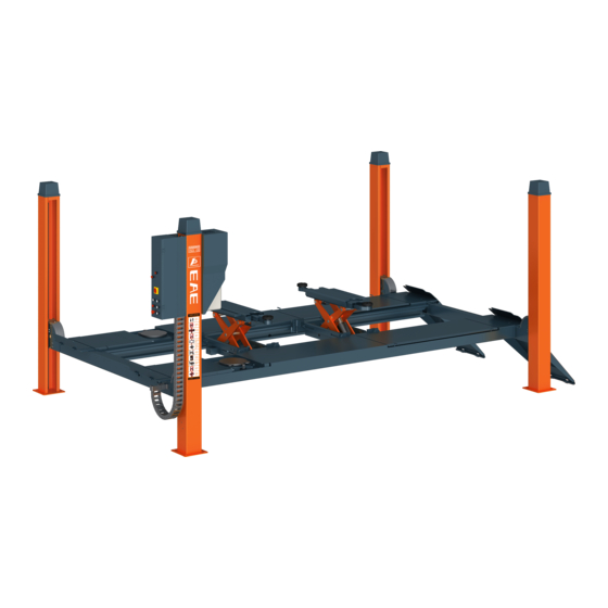
- Page 1 EE-6435V2.B.PD Installation, Operation Four Post Lift and Parts Manual Electrical Release With play detector Lifting capacity: 4000KG/5000KG Distributed by Please read this entire manual carefully and completely before installation or operation of the lift.
- Page 2 Installation, Operation and Parts Manual EE-6435V2.B.PD IMPORTANT NOTES Before start up, connecting and operating EAE products, it is absolutely essential that the operating instructions/owner’s manual and, in particular the safety instructions are studied carefully. By doing so you can eliminate any uncertainties in handling EAE products and thus associated safety risks up front; something which is in the interest of you own safety and will ultimately help avoid damage to the device, When an EAE product is handed over to another person, not only the operating instructions but also the safety instructions and information on its designated use must be handed over to the person. By using the product you agree the following conditions: Copy right The enclosed instructions are the property of EAE or its supplier, and are protected against duplication and reproduction by copyright laws, international agreements, and other domestic legislation. The reproduction or disclosure of instructions or an extract thereof is prohibited and offenders are liable to prosecution; EAE reserves the right or initiates criminal proceedings and asserts claims for damages in the event of infringements. Warranty The use of non‐approved hardware will result in a modification of our products and thus to the exclusion of any liability or warranty, even if such hardware has been removed again in the interim. It is not permissible to make any changes to our products and these are not only to be used together with genuine accessories and genuine replacement parts. Otherwise any warranty claims will be invalid. Liability The liability of EAE is limit to the amount that the customer has actually paid for this product. This exclusion of liability does not apply to damages caused through willful misconduct or gross negligence on the part of EAE. All information in this manual is believed to be correct at time of publication. EAE reserves the right to amend and alter technical data and composition without prior notice. Please confirm at time of ordering. ...
-
Page 3: Table Of Contents
Installation, Operation and Parts Manual EE-6435V2.B.PD IMPORTANT NOTES ................................ 2 SAFETY NOTES ................................ 4 1.1 Operation of lifting platforms .............................. 4 1.2 Checking of the lifting platforms ............................ 4 1.3 Important safety notices .............................. 5 1.4 Safety advices .................................. 6 1.5 Risks and safety instructions .............................. 7 1.6 Noise level .................................... 9 PACKING, STORAGE AND TRANSPORTATION ......................... 10 2.1 The lift was dismantled into the following 2 parts for transportation. ................ 10 2.2 Storage .................................... 10 2.3 Lifting and handling ................................ 10 PRODUCTS DESCRIPTIONS ............................. 11 3.1 General descriptions ................................ 11 ... -
Page 4: Safety Notes
Installation, Operation and Parts Manual EE-6435V2.B.PD SAFETY NOTES 1.1 Operation of lifting platforms This lift is specially designed for lifting motor vehicles. Users are not allowed to use it for any other purposes. The applicable national regulations, laws and directives must be observed. Only users aged 18 or above who have been instructed on how to operate the lifting platform and have proven their ability to do so to the owner are to be entrusted with unsupervised operation of lifting platforms. The task of operating the lifting platforms must be granted in writing. Before loading a vehicle onto the lifting platform, users should study the original operation instructions and familiarize themselves with the operating procedures in several trial runs. Lift vehicle within the rated load. Don’t attempt to raise vehicles with excessive weight. 1.2 Checking of the lifting platforms Checks are to be based on the following directives and regulations: Basic principles for testing lifting platforms The basic safety requirements stipulated in the directive 2006/42/EC The applicable accident prevention regulations The checks are to be organized by the user of the lifting platform. The user is responsible for appointing an expert or qualified person to perform checking. It must be ensure that the person chosen satisfies the requirements. The user bears special responsibility if employees of the company are appointed as experts or qualified persons. 1.2.1 Scope of checking ... -
Page 5: Important Safety Notices
Installation, Operation and Parts Manual EE-6435V2.B.PD 1.3 Important safety notices 1.3.1 Recommend for indoor use only, DO not expose the lift to rain, snow or excessive moisture. 1.3.2 Only use this lift on a surface that is stable, level and dry and not slippery, and capable of sustaining the load. Do not install the lift on any asphalt surface. 1.3.3 Read and understand all safety warnings before operating the lift. 1.3.4 Do not leave the controls while the lift is still in motion. 1.3.5 Keep hands and feet away from any moving parts. Keep feet clear of the lift when lowering. 1.3.6 Only these properly trained personnel can operate the lift. 1.3.7 Do not wear unfit clothes such as large clothes with flounces, tires, etc., which could be caught by moving parts of the lift. 1.3.8 To prevent evitable incidents, surrounding areas of the lift must be tidy and with nothing unconcerned. 1.3.9 The lift is simply designed to lift the entire body of vehicles, with its maximum weight within the lifting capacity. 1.3.10 Always insure the safety locks are engaged before any attempt to work near or under the vehicle. Never remove safety related components from the lift. Do not use if safety related components are damaged or missing. 1.3.11 Do not rock the vehicle while on the lift or remove any heavy component from vehicle that may cause excessive weight shift. 1.3.12 Check at any time the parts of the lift to ensure the agility of moving parts and the performance of synchronization. Ensure regular maintenance and if anything abnormal occurs, stop using the lift immediately and contact our dealers for help. 1.3.13 Lower the lift to its lowest position and do remember to cut off the power source when service finishes. 1.3.14 Do not modify any parts of the lift without manufacturer’s advice. 1.3.15 If the lift is going to be left unused for a long time, users are required to: a. Disconnect the power; b. Empty the oil tank; c. Lubricate the moving parts with hydraulic oil. WARNING:The warnings, cautions and instructions discussed in this instruction manual cannot cover all possible conditions and situations that may occur. It must be understood by the operator that common sense and caution are factors which cannot be built into this product, ... -
Page 6: Safety Advices
Installation, Operation and Parts Manual EE-6435V2.B.PD 1.4 Safety advices All safety warning labels are clearly depicted on the lift to ensure that the operator is aware of and avoid the dangers of using the lift in an incorrect manner. The labels must be kept clean and they have to be replaced if detached or damaged. Please read carefully the meaning of each label and memories them for future operation. ... -
Page 7: Risks And Safety Instructions
Installation, Operation and Parts Manual EE-6435V2.B.PD 1.5 Risks and safety instructions During lift functioning, the operator must remain in the control station as defined in figure 1. The presence of persons beneath the cross‐pieces and/or the platforms when they are moving, or the presence of persons inside the danger zone indicated in figure 2 is strictly prohibited. The area occupied from the lift and its surrounding width 1, 2 meters of the lift are defined as “DANGER ZONE”. The operator parking area, only for operating the lift, is defined as “OPERATEOR ZONE”. During operations persons are admitted to the area beneath the vehicle only when the vehicle is already in the elevated position, when the cross‐pieces and platforms are stationary, and when the mechanical safety devices (wedges) are firmly engaged in the slots on the safety rods. (Fig. 1) (Fig. 2) RISK OF CRUSHING (OPERATOR) Possible if the operator controlling the lift is not in the specified position at the control panel. When the platforms (and vehicle) are lowering the operator must never be partly or completely underneath or near of the movable structure. Always remain in the operator zone (Fig. 3). (Fig. 3) Operator zone ... - Page 8 Installation, Operation and Parts Manual EE-6435V2.B.PD RISK OF CRUSHING (PERSONNEL) When the platforms and the vehicle are lowering personnel are prohibited from entering the area beneath the movable parts of the lift (Fig.4). The lift operator must not start the lift until it has been clearly established that there are no persons in danger zone (Fig 1, 4, 5) (Fig. 4) (Fig.5) ...
-
Page 9: Noise Level
Installation, Operation and Parts Manual EE-6435V2.B.PD RISK OF SLACKENING OF LIFT CABLES Caused by objects left leaning against the posts or on the platforms. (Fig. 9) (Fig.8) risk of vehicle falling (Fig.9) risk of slackening of lift cables. ... -
Page 10: Packing, Storage And Transportation
Installation, Operation and Parts Manual EE-6435V2.B.PD PACKING, STORAGE AND TRANSPORTATION Packing, lifting, handling, transporting operations must be performed only by experienced personnel with appropriate knowledge of the lift and after reading this manual. 2.1 The lift was dismantled into the following 2 parts for transportation. Name Packed by Dimension Weight Quantity Lift(48L) Steel brackets 5150*740*710 1500KG 1 Lift(52L) Steel brackets 5550*740*710 1650KG 1 Lift(57L) Steel brackets 6050*740*710 1850KG 1 Ramps Bubbled film ... -
Page 11: Products Descriptions
Installation, Operation and Parts Manual EE-6435V2.B.PD PRODUCTS DESCRIPTIONS 3.1 General descriptions This four post lift is generally composed by four posts, two beams, two platforms, a hydraulic oil cylinder and a set of power unit. It is driven by an electro‐hydraulic system. Up and down of platforms is controlled by the to and fro movement of the oil cylinder. To ensure safety for operators, it is equipped with mechanical safety locks in the four posts , which will automatically engaged in the process of lifting so as to ... -
Page 12: Dimensions
Installation, Operation and Parts Manual EE-6435V2.B.PD 3.3 Dimensions MODEL DATA 48L 52L 57L RL 4880 5280 5780 OL 5970 6370 6870 CL 4888 5288 5788 CL1 4438 4838 5338 L1 1580 1980 2280 L2 970 ... -
Page 13: Safety Devices Descriptions
Installation, Operation and Parts Manual EE-6435V2.B.PD 3.4 Safety devices descriptions NO. Safety Device Function 1 Safety rod Ensure mechanical safety in the rising and lowering process and lock the 2 Safety block A lifting platform at expected height. 3 Safety block B 4 Electromagnet Release the safety lock. 5 Limit switch Cut off power supply in case the cable slacks. 6 Rising limit switch ... -
Page 14: Technical Data
Installation, Operation and Parts Manual EE-6435V2.B.PD 3.5 Technical data Item Data Power Form Electro‐hydraulic Rated capacity of the lifting platform 4000KG(48L/52L), 5000KG(48L/52L/57L) Full rise height of the main lift 1850mm Initial height of the main lift 225mm Full rise time of the main lift ≤70S Full lowering time of the main lift ≤60S Rated capacity of the PD 4000kg Working pressure Main lift ≥20MPa;PD ≥24MPa Electricity ... -
Page 15: Installation Instructions
Installation, Operation and Parts Manual EE-6435V2.B.PD INSTALLATION INSTRUCTIONS 4.1 Preparations before installation 4.1.1 Space requirements. Refer to 3.3 for the dimensions of the lift. There must also be a clearance of at least 0.6m between the lifting platform and fixed elements (e.g. wall) in all lifting positions. There must be sufficient space at the ends of the lifting platform for driving vehicles on and off. To stop vehicles colliding with the ceiling, it is advisable to fit an overhead light barrier in low ceiling buildings. 4.1.2 Foundations and connections The user must have the following work performed before erecting the lift. Construction of the foundation following consultation with the manufacturer’s customer service or an authorized service agent. Routing of the wiring to the installation location. The user must provide fuse protection for the connection. Requirements for power 2 2 supply cable of the installation site: at least 2.5mm wire core for 3Ph power and 4.0mm wire core for 1Ph power. Attention: electrical system connection must be done by licensed technicians. Refer also to the corresponding information on the name plate and in the operation instructions. Before doing electrical connection, make sure the lift is electrically adapt to the local power supply. ... - Page 16 Installation, Operation and Parts Manual EE-6435V2.B.PD 4.1.3 Foundations preparations Indoor installation only. There must also be a clearance of at least 0.6 meter between the lifting platform and fixed elements (e.g. wall) in all lifting positions. There must be sufficient space for driving vehicles on and off. C20/25 concrete base with strength more than 3000psi, Minimum thickness of 200mm. Surface: Horizontal and even (Gradients max. 0.5 %) Newly built concrete ground must be older than 20days. In mm. Platform length L 48L 4888 52L 5288 57L 5788 ...
- Page 17 Installation, Operation and Parts Manual EE-6435V2.B.PD 4.1.4 Tools and equipment needed for installation Tool name Specification Quantity needed Electrical drill With D16 and D18 drill bit. 1 Open spanner D17‐19mm 2 Adjustable spanner bigger than D30mm 1 Cross socket screw driver PH2 1 Quick spanner handle adapter/ Ratchet 1 Socket spanner D24mm 1 Levelling device 1 Hammer 10 pounds ...
-
Page 18: Installation Attentions
Installation, Operation and Parts Manual EE-6435V2.B.PD S/N Name Qty 24 Ramp shaft 2 25 Expansion bolt 16 26 Control cabinet 1 27 Power unit 1 28 Manual 1 29 Drive‐on ramp 2 4.2 Installation attentions 4.2.1 Joints of oil hose and wiring must be firmly connected in order to avoid leakage of oil hose and looseness of electrical wires. 4.2.2 All bolts should be firmly screwed up. ... - Page 19 Installation, Operation and Parts Manual EE-6435V2.B.PD Step 5: Connect posts and crossbeams. 1. Pull up the safety ladder from the post with its bottom end higher than the height of cross beam. 2. Pull the post to the cross beam as the direction arrow showed in the following drawing. Fasten the top end of safety ladders to the top plate of each post. 3. Pull out the steel cables from both ends of the cross beam and fasten them on the top plate of post. (Please see the Annex for the steel cable connection) ...
- Page 20 Installation, Operation and Parts Manual EE-6435V2.B.PD Step 6: Fit on 8 nylon sliders and 4 protection covers. 1. Fasten the slider to its holder and then connect the slider holder and the cross beam. 2. Fix protection covers. Step 7: Fix the drive‐on ramps. Align the end of the platform and the hole on the ramp and connect them with shaft and cotter pins. Step 8: Fit on four post caps on top of the four posts. Step 9: Connect the electrical and hydraulic system. Refer to electrical and hydraulic connection diagrams before making connection. Attention: electrical system connection must be done by licensed technicians. (For three phase power supply, if the lift doesn't raise and the motor may turn in the wrong direction, in such event, interchange wires U, V in the control cabinet). Step 10: Fill with hydraulic oil. ONLY CLEAN AND FRESH OIL ONLY .Lift must be fully lowered before changing or adding hydraulic oil. Pour 10 liters anti‐abrasion hydraulic oil into the oil tank. The level of oil shall reach the tippets volume mark of the tank. Run the lift for several cycles and add more oil until the lifting platform can reach its maximum height. Note:It is recommended to use NO.46 hydraulic oil when average temperature of the location is above 18 degree Celsius and using NO.32 hydraulic oil when temperature is below 18 degree Celsius. Change the oil 6 months after initial use and change once per year thereafter. Step 11: Levelling ...
- Page 21 Installation, Operation and Parts Manual EE-6435V2.B.PD Secondly, level the platforms after mechanical safety locks are engaged. Raise the platform about 750mm‐800mm high and check if the safety blocks in the four posts could be engage synchronously. If not, adjust screw ①to ensure the synchronization. Step 12: Adjust limit switches for out of level protection system. Make the platform be locked at height of 800mm and adjust the limit switch as showed in the following drawing with hex socket spanner (3mm) ...
-
Page 22: Items To Be Checked After Installation
Installation, Operation and Parts Manual EE-6435V2.B.PD Step 14: Trial running. Get familiar with lift controls by running the lift through a few cycles before loading vehicle on lift. This step is of particular importance for it can check if the oil hose is well connected. The connection is qualified when there is no abnormal sound or leakage after having been tested for 5‐6 times. Raise and lower lift several times. The cylinder is self‐bleeding. After bleeding system, fluid level in power unit reservoir may be down. Add more fluid if necessary to raise lift to full height. It is only necessary to add fluid to raise lift to full height. If the lift doesn't raise, the motor may turn in the wrong direction. In such event, interchange wires U, V in the connection box. 4.4. Items to be checked after installation S/N Check items YES NO 1 Screw torque of expansion bolts : 60‐80N•m; 2 Rising speed ≥20mm/s; 3 Noise with rated load ≤75db; 4 Grounding resistance: not bigger than 4Ω; 5 Height difference of the two platform ≤5mm; ... -
Page 23: Descriptions Of Control Panel
Installation, Operation and Parts Manual EE-6435V2.B.PD 5.2 Descriptions of control panel POS. Name Function FA Alarm buzzer Low height warning QS Power switch Power on/ off HL Power indicator Display if electricity is connected SB1 UP button Control the rising movement SB3 DOWN I button Control the initial lowering movement 1.1 In case the clearance between the platform and the floor is more than 300mm, press DOWN II button to lock the platform. SB2 Safety lock /DOWN II button 1.2 In case the clearance between the platform and the floor is less than ... -
Page 24: Flow Chart For Operation
Installation, Operation and Parts Manual EE-6435V2.B.PD 5.3 Flow chart for operation 5.4 Operation instructions The lift must be only used in a static position for lifting and lowering vehicles. Only use this lift on a surface that is stable and capable of sustaining the load. Do not install the lift on any asphalt surface. To avoid personal injury and/or property damage, permit only trained personnel to operate the lift. After reviewing these instructions, get familiar with lift controls by running the lift through a few cycles before loading vehicle on lifting platform. 5.4.1 Use the main lifting platform Turn the selection switch to the mode of “LIFT” Raise the lift Make sure vehicle is neither front nor rear heavy and center of balance should be centered over the lift. 1. Turn on the power switch. 2. Park the vehicle on the platforms to ensure its gravity is positioned midway of the platforms. 3. Push the UP button until rise to the expected height. 4. Before perform any service around or under the vehicle, push the safety lock button to ensure the mechanical safety lock is fully engaged. Turn off the power so as to avoid any wrong operation done by irrelevant personnel and check again the stability of the vehicle. Lower the lift Pay careful attention that all personnel and objects are kept clear. 1. Turn on the power switch. 2. Push “DOWN I” button to lower the lift. It will stop lowering at proper height off the ground. 3. Push “DOWN II” button to continue lowering the platforms which accompanies with safety alarming buzz. ... - Page 25 Installation, Operation and Parts Manual EE-6435V2.B.PD 5.4.2 Use the play detector Turn the selection switch to the state of “PD” The PD is designed for powered moving the wheels of the vehicle enabling inspection of suspension and steering joints. 1. Ensure vehicle is positioned centrally on the PD plates, steering lock off and engine running (to enable the power steering system) 2. Raise lift to desired working height to enable you to clearly view the suspension / steering joints to be inspected and park the lift into the mechanical locking system. 3. Using either the inspection torch or the key fob, Pressing and holding the left button will operate the nearside PD plate (rotation of steering) from extent to extent, once button released plates will return to the center position. Pressing and holding the Right button will operate the offside PD plate (side to side movement) from extent to extent, once button released plates will return to the center position. If the rechargeable LED torch style remote control is chosen allow to charge for 3 hours before initial use, always replace it back to its holder to have it charged when not in use. Attention: the remote control works within a radius of 5.7m from the main control box. ...
-
Page 26: Emergency Lowering In Case Of No Power
Installation, Operation and Parts Manual EE-6435V2.B.PD 5.5 Emergency lowering in case of no power In the case the safety lock is not engaged: 1. Push the front rod of the four electromagnets under the cross beam to have the four safety blocks released from the safety rods. Front rod of electromagnet Safety block and safety rods 2. Press and screw loose counter‐clockwise the unloading valve to lower the platform. Unloading valve ... -
Page 27: Trouble Shooting
Installation, Operation and Parts Manual EE-6435V2.B.PD TROUBLE SHOOTING ATTENTION: If the trouble could not be fixed by yourself, please do not hesitate to contact us for help .We will offer our service at the earliest time we can. By the way, your troubles will be judged and solved much faster if you could provide us more details or pictures of the trouble. TROUBLES CAUSE SOLUTION Abrasion exists on insider surface of the posts. Grease the inside of the post. Abnormal noise Trash in the post. Clear the trash Loose wire connection Check and make a good connection. Motor does not run Blown motor. Replace it. and will not rise Damaged limit switch or its wire connection is loose. Adjust or replace the limit switch. The motor run reversely. Check the wire connection. Overflow valve is not well screwed up or jammed. Clean or make adjustment Damaged gear pump. Replace it. Motor runs but will not rise Too low oil level. ... -
Page 28: Maintenance
Installation, Operation and Parts Manual EE-6435V2.B.PD MAINTENANCE Easy and low cost routine maintenance can ensure the lift work normally and safely. Following are requirements for routine maintenance. Follow the below routine maintenance schedule with reference to the actual working condition and frequency of your lift. LUBRICATE moving parts with lithium grease. S/N Components Methods Period Check if control buttons work as "hold‐ to ‐run " and check if they 1 Control buttons Every day work as the function indicated. Push the UP button, check and ensure the four mechanical safety Synchronization of the ascending 2 blocks give off sound simultaneously. Both runways shall rise Every day movement steadily without abnormal sounds. Push the LOCK button, inspect and ensure the four mechanical Synchronization of mechanical ... - Page 29 Installation, Operation and Parts Manual EE-6435V2.B.PD S/N Components Methods Period Push the DOWNI button. Inspect and ensure the runways stop 6 Safety lowering limit switch lowering at safety height (300mm) and then push DOWN II button Every week to have the platform fully lowered. Remove the motor housing. ...
-
Page 30: Annex 1, Steel Cable Connection
Installation, Operation and Parts Manual EE-6435V2.B.PD Annex 1, Steel cable connection ... -
Page 31: Annex 2, Hydraulic Schemes And Parts List
Installation, Operation and Parts Manual EE-6435V2.B.PD Annex 2, Hydraulic schemes and parts list 1.Oil tank 2.Oil sucking filter 3.Gear pump 4.Coupling 5.Motor 6.Composite hydraulic block 7.Cushion valve 8.Over‐flow valve 9.Single way valve 10.Solenoid unloading valve 11.Pressure supplementing valve 12.Oil tank cover 13.Throttle valve 14.Solenoid valve 15.Solenoid valve ... - Page 32 Installation, Operation and Parts Manual EE-6435V2.B.PD POS. Code Name Specification Qty Remark 1 Hydraulic unit EE‐6435E.PD 1 2 624001021 Oil hose L=4900mm 1 48L /52L 2 624001082 Oil hose L=5000mm 1 57L 3 ...
- Page 33 Installation, Operation and Parts Manual EE-6435V2.B.PD POS. Code Name Specification Qty Remark 10 624001123 Oil hose L=4400mm 1 57L 11 310102013 90 connector with swivel 08N‐M14S 1 48L/52L/57L 12 615018001 Right angle throttle valve MR30‐A24‐B16 1 48L/52L/57L 13 615027005 ...
- Page 34 Installation, Operation and Parts Manual EE-6435V2.B.PD POS. CODE Name Specification Qty 1 320201005 Motor 400V‐2.2KW ‐3PH‐50HZ‐2P 1 320203001 Motor 380V‐3.5KW ‐3PH‐50HZ‐2P 2 310102013 90 degree connector with swivel 08N‐M14S 1 3 330405012 Oil tank 12L 1 4 ...
-
Page 35: Annex 3, Electrical Schemes And Parts List
Installation, Operation and Parts Manual EE-6435V2.B.PD Annex 3, Electrical schemes and parts list ... - Page 36 Installation, Operation and Parts Manual EE-6435V2.B.PD ...
- Page 37 Installation, Operation and Parts Manual EE-6435V2.B.PD ...
- Page 38 Installation, Operation and Parts Manual EE-6435V2.B.PD ...
- Page 39 Installation, Operation and Parts Manual EE-6435V2.B.PD ...
- Page 40 Installation, Operation and Parts Manual EE-6435V2.B.PD ...
- Page 41 Installation, Operation and Parts Manual EE-6435V2.B.PD ...
- Page 42 Installation, Operation and Parts Manual EE-6435V2.B.PD Pos. CODE Name Qty T 320102023 Transformer (dual 400‐230V) 1 320101080 Transformer (400V) SQ1;SQ2 320301009 Limit switch 2 SQ3‐SQ6 320301011 Limit switch 4 SQ7;SQ8 320302002 Proximity switch 2 SA1 320303010 ...
-
Page 43: Annex 4,Exploded Drawings And Parts List
Installation, Operation and Parts Manual EE-6435V2.B.PD Annex 4,Exploded drawings and parts list Pos. CODE Name QTY NOTE 1 Power side post B 1 2 Secondary post 3 3 Power side crossbeam 1 4 Secondary crossbeam ... - Page 44 Installation, Operation and Parts Manual EE-6435V2.B.PD Pos. CODE Name QTY NOTE 19 208101001 Steel cable clip 4 20 615027038B Steel cable 2 48L 615027037B Steel cable 2 52L 615027036 Steel cable 2 57L ...
- Page 45 Installation, Operation and Parts Manual EE-6435V2.B.PD Pos. CODE Name QTY NOTE 1 614027703 Power side post 1 1 614027091B Secondary post 3 2 612027001B Safety rod 4 3 420270140 Clip of safety rod 8 4 420270090 Post cap ...
- Page 46 Installation, Operation and Parts Manual EE-6435V2.B.PD Pos. CODE Name QTY NOTE 34 202101009 Cross socket cap head screw M4*14 6 Pos. CODE Name QTY NOTE 1 614027613 Main crossbeam 1 1 614027614 Secondary crossbeam ...
- Page 47 Installation, Operation and Parts Manual EE-6435V2.B.PD Pos. CODE Name QTY NOTE 15 410270031B Small pulley 4 16 410270630 Spring 4 17 410270051D Safety block B1 2 18 410270061 Adjustable rod A 4 19 ...
- Page 48 Installation, Operation and Parts Manual EE-6435V2.B.PD Pos. CODE Name QTY NOTE 53 203101007 Hex nut M12 4 54 202109087 Hex socket cylinder head screw M12*70 4 55 202111004 Hex socket flat head screw M8*12 8 56 202101009 Cross socket cap head screw M4*14 2 Pos. CODE ...
- Page 49 Installation, Operation and Parts Manual EE-6435V2.B.PD Pos. CODE Name QTY NOTE 9 410270101B Shaft retaining block 2 10 202110004 Hex socket button head screw M 8*12 4 11 208106001 Straight pressed oil cup 2 12 202109060 Hex socket button head screw M12*145 4 GB/T 70 13 615027005 ...
- Page 50 Installation, Operation and Parts Manual EE-6435V2.B.PD Pos. CODE Name QTY NOTE 44 203101004 Hex nut M6 24 45 Auxiliary lifting platform (secondary) 1 46 Auxiliary lifting platform (main) 1 47 320301009 Limit switch 8104 1 48 202109026 Hydraulic block ...
Need help?
Do you have a question about the EE-6435V2.B.PD and is the answer not in the manual?
Questions and answers