Table of Contents
Advertisement
Quick Links
Advertisement
Table of Contents

Subscribe to Our Youtube Channel
Related Manuals for EAE EE-612FE


Summary of Contents for EAE EE-612FE
-
Page 1: Important Notes
Installation, Operation and Parts Manual Model No. EE-612FE Fixed type single post lift Electrical Release Lifting Capacity 2500KG Please read this entire manual carefully and completely before installation or operation of the lift. 2017.08.18 - 540104118... - Page 2 Liability The liability of EAE is limit to the amount that the customer has actually paid for this product. This exclusion of liability does not apply to damages caused through willful misconduct or gross negligence on the part of EAE...
-
Page 3: Table Of Contents
Installation, Operation and Parts Manual EE-612FE IMPORTANT NOTES............................1 SAFETY NOTES ..............................4 1.1 Operation of lifting platforms ..........................4 1.2 Checking of the lifting platforms ..........................4 1.3 Important safety notices ............................5 1.4 Warning labels ............................... 6 1.5 Potential safety risks .............................. 7 1.6 Noise level ................................ -
Page 4: Safety Notes
Installation, Operation and Parts Manual EE-612FE SAFETY NOTES 1.1 Operation of lifting platforms This lift is specially designed for lifting motor vehicles. Users are not allowed to use it for any other purposes. The applicable national regulations, laws and directives must be observed. -
Page 5: Important Safety Notices
Installation, Operation and Parts Manual EE-612FE rules of engineering to be able to check and give an expert option on lifting platforms. 1.3 Important safety notices 1.3.1 Recommend for indoor use only, DO not expose the lift to rain, snow or excessive moisture. -
Page 6: Warning Labels
Installation, Operation and Parts Manual EE-612FE 1.4 Warning labels All safety warning labels are clearly depicted on the lift to ensure that the operator is aware of and avoid the dangers of using the lift in an incorrect manner. The labels must be kept clean and they have to be replaced if... -
Page 7: Potential Safety Risks
Installation, Operation and Parts Manual EE-612FE 1.5 Potential safety risks 1.5.1 Mains voltage nsulation damage and other faults may result in accessible components being live Safety measures: Only ever use the power cord provided or a tested power cord. -
Page 8: Packing, Storage And Transportation
Installation, Operation and Parts Manual EE-612FE PACKING, STORAGE AND TRANSPORTATION Packing, lifting, handling, transporting operations must be performed only by experienced personnel with appropriate knowledge of the lift and after reading this manual. 2.1 Storage The packs must be kept in a covered and protected area in a temperature range 0f -10℃to +40℃. They must not be exposed to direct sunlight, rain or water. -
Page 9: Product Descriptions
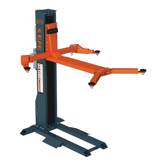
Installation, Operation and Parts Manual EE-612FE PRODUCT DESCRIPTIONS 3.1 General descriptions This single post lift is for fixed use and is driven by an electro-hydraulic system. Gear pump delivers hydraulic oil to oil cylinders and pushes upwards its piston. The piston drives the chain to raise the carriage and lifting platforms. -
Page 10: Dimensions
Installation, Operation and Parts Manual EE-612FE 4.3 Dimensions... -
Page 11: Safety Devices Descriptions
Installation, Operation and Parts Manual EE-612FE 3.4 Safety devices descriptions POS. Name Function 24V control unit Safe voltage for users. Mechanical safety catch Catch the carriage in case of hydraulic failure. Safe descent limit switch Stop descending at safety height off the ground. -
Page 12: Installation Instructions
Installation, Operation and Parts Manual EE-612FE INSTALLATION INSTRUCTIONS 4.1 Preparations before installation 4.1.1 Space requirements. Indoor installation only. Refer to 3.3 for the dimensions of the lift. There must also be a clearance of at least 1 meter between the lifting platform and fixed elements (e.g. -
Page 13: Installation Attentions
Installation, Operation and Parts Manual EE-612FE 4.1.5 Checking parts Unfold the package and check if any parts missed as per the following list. Do not hesitate to contact us in case any parts missed, but if you do not contact us and insist installing upon the lack of some parts, we as well as our dealers will not bear any responsibility for this and will charge for any parts subsequently demanded by the buyer. - Page 14 Installation, Operation and Parts Manual EE-612FE Step 2: Fix the bridge approach with the base frame Step 3: Fix the post onto to the base frame.
- Page 15 Installation, Operation and Parts Manual EE-612FE Step 4: Drill anchor holes for expansion bolts and secure the base frame on the ground with anchoring expansion bolts. Step 5: Install the lifting platform and lifting arms. a) Fix the lifting platform onto the carriage with 10 flat washers, spring washers and hex head screws.
- Page 16 Installation, Operation and Parts Manual EE-612FE b) Fix lifting arms onto the lifting platform. Step 6: Fix the mechanical safety locking unit.
- Page 17 Installation, Operation and Parts Manual EE-612FE Step 7: Mount the power unit onto the post. Step 8: Connect oil hoses. Connect the oil hose as per the following diagram. Make sure the oil hose connector is clean before making the connection.
- Page 18 Installation, Operation and Parts Manual EE-612FE Step 9: Fix control system a) Mount the control box onto the post. b) Fix limit switches and do wire connections.
- Page 19 Installation, Operation and Parts Manual EE-612FE c) Connect wires of electromagnets. d) Connect wires of motor and solenoid unloading valve.
- Page 20 Installation, Operation and Parts Manual EE-612FE Step 10: Fix chain protection cloth Step 11: Fill with hydraulic oil. CLEAN AND FRESH OIL ONLY. DON’T FILL THE TANK COMPLETELY FULL. Lift must be fully lowered before changing or adding hydraulic oil Pour 7 liters anti-abrasion hydraulic oil into the oil tank.
-
Page 21: Items To Be Checked After Installation
Installation, Operation and Parts Manual EE-612FE 4.4 Items to be checked after installation. Check items Rising speed ≥20mm/s; Noise with rated load ≤75db; Grounding resistance: not bigger than 4Ω; If the control button works as “hold to run”? If limit switches work well? -
Page 22: Operation Instructions
Installation, Operation and Parts Manual EE-612FE 5.3 Operation instructions WARNING!Loads must be centered on platform all times. WARNING!The lift must be only used in a static position for lifting and lowering vehicles. Pos. Name Function Alarm buzzer Safety descent warning... -
Page 23: Trouble Shooting
Installation, Operation and Parts Manual EE-612FE TROUBLE SHOOTING ATTENTION: If the trouble could not be fixed by yourself, please do not hesitate to contact us for help .We will offer our service at the earliest time we can. By the way, your troubles will be judged and solved much faster if you could provide us more details or pictures of the trouble. -
Page 24: Maintenance
Installation, Operation and Parts Manual EE-612FE MAINTENANCE Easy and low cost routine maintenance can ensure the lift work normally and safely. Following are requirements for routine maintenance. Follow the below routine maintenance schedule with reference to the actual working condition and frequency of your lift. - Page 25 Installation, Operation and Parts Manual EE-612FE Components Methods Period Check if control buttons work as "hold- to -run " and check if Control buttons Every day they work as the function indicated. Check if mechanical catch can engage and disengage effectively...
-
Page 26: Annex 1, Floor Plan
Installation, Operation and Parts Manual EE-612FE Annex 1, Floor Plan See Annex 1 for foundation plan. There must be a clearance of at least 1 meter between the lifting platform and fixed elements (e.g. wall) in all lifting positions. There must also be sufficient space for driving vehicles on and off. -
Page 27: Annex 2, Electrical Schemes And Parts List
Installation, Operation and Parts Manual EE-612FE Annex 2, Electrical schemes and parts list... - Page 28 Installation, Operation and Parts Manual EE-612FE...
- Page 29 Installation, Operation and Parts Manual EE-612FE...
- Page 30 Installation, Operation and Parts Manual EE-612FE POS. Code Name Specification 320101011 Transformer -220V JBK3-63VA 220V-24V 320101013 Transformer -230V JBK3-63VA 230V-24V 320101014 Transformer -240V JBK3-63VA 240V-24V 320101016 Transformer -380V JBK3-63VA 380V-24V 320101017 Transformer -400V JBK3-63VA 400V-24V 320101018 Transformer -415V JBK3-63VA 415V-24V Motor 2.2KW...
-
Page 31: Annex 3, Hydraulic Schemes And Parts List
Installation, Operation and Parts Manual EE-612FE Annex 3, Hydraulic schemes and parts list 1. Drive oil cylinder 3. Solenoid unloading valve 4. Throttle valve 5. Motor 6. Coupling 7. Gear pump 8. Single –way valve 9. Over-flow valve 10. Anti-surge valve 11. - Page 32 Installation, Operation and Parts Manual EE-612FE POS. Code Name Specification Power unit 2.2kW 624001042B φ8 Rubber oil hose L=400mm 615022014 612 right angle connector 612E-A8 615022013 Long oil hose (2050mm) 612E-A12 615015003 Composite connector 6255E-A7-B7 615022012B 612 oil cylinder 612E-A6-B1...
- Page 33 Installation, Operation and Parts Manual EE-612FE...
- Page 34 Installation, Operation and Parts Manual EE-612FE POS. Code Name Specification 330405019 Oil tank 330101063B Hydraulic block YF-2D(XLFKG-F) 330308006 Solenoid unloading valve DHF06-220H/DC24 330304001 Over flow valve EYF-C 330302001 Single way valve DYF-C 330305002 Throttle valve TC-VF 207103019 Composite seal ring...
-
Page 35: Annex 4, Mechanical Exploded Drawings And Parts List
Installation, Operation and Parts Manual EE-612FE Annex 4, Mechanical exploded drawings and parts list POS. Code Name Specification 614022001 Stationary base frame 612FE-A1-B1 202111005 Hex socket flat head screw M8*15 614022002 Drive-on approach 612FE-A1-B2 201201008 Expansion bolt M18*200 614022002 Drive-on approach... - Page 36 Installation, Operation and Parts Manual EE-612FE...
- Page 37 Installation, Operation and Parts Manual EE-612FE POS. Code Name Specification 410222533 Top connection plate 612E-A2-B3 204201006 Spring washer 202109085 Hex socket cylinder head screw M12*30 204101007 Flat washer 202101009 Cross socket cap head screw M4*14 320301011 Limit switch TZ-8108 TZ-8108...
- Page 38 Installation, Operation and Parts Manual EE-612FE POS. Code Name Specification 204101009 M16 flat washer 204201010 M16 spring washer 201103007 Hex head full swivel screw M16*45 612022008 Pulling rod assembly 612E-A5-B25 206102007 Elastic post pin 5*50 410150921 Teeth block 6255E-A3-B5 410221410...
- Page 39 Installation, Operation and Parts Manual EE-612FE POS. Code Name Specification 410220021 Spring 612E-A4-B7 615022019 Left handle 612E-A4-B8 612022001 Front fixing shaft 612E-A4-B5 202109085 Hex socket cylinder head screw M12*30 614022018C Lifting platform assembly 612E-A4-B1 Optional Drive-on approach POS. Code Name...
Need help?
Do you have a question about the EE-612FE and is the answer not in the manual?
Questions and answers