Table of Contents
Advertisement
Advertisement
Table of Contents

Related Manuals for EAE EE-MR35


Summary of Contents for EAE EE-MR35
- Page 1 Installation, Operation and Parts Manual Model No. EE-MR35 Short Platform Scissor Lift Mid Rise Pneumatic Release Lifting Capacity, 3500KG Please read this entire manual carefully and completely before installation or operation of the lift. 2017.09.01 - 540104122...
-
Page 2: Important Notes
Liability The liability of EAE is limit to the amount that the customer has actually paid for this product. This exclusion of liability does not apply to damages caused through willful misconduct or gross negligence on the part of EAE. -
Page 3: Table Of Contents
Installation, Operation and Parts Manual EE-MR35 IMPORTANT NOTES .............................. 2 SAFETY NOTES ..............................4 1.1 Operation of lifting platforms ............................4 1.2 Checking of the lifting platforms ..........................4 1.3 Important safety notices .............................. 5 1.4 Warning labels ................................6 1.5 Potential safety risks .............................. -
Page 4: Safety Notes
Installation, Operation and Parts Manual EE-MR35 SAFETY NOTES 1.1 Operation of lifting platforms This lift is specially designed for lifting motor vehicles. Users are not allowed to use it for any other purposes. The applicable national regulations, laws and directives must be observed. -
Page 5: Important Safety Notices
Installation, Operation and Parts Manual EE-MR35 engineering to be able to check and give an expert option on lifting platforms. 1.3 Important safety notices 1.3.1 Recommend for indoor use only. DO not expose the lift to rain, snow or excessive moisture. -
Page 6: Warning Labels
Installation, Operation and Parts Manual EE-MR35 1.4 Warning labels All safety warning labels are clearly depicted on the lift to ensure that the operator is aware of and avoid the dangers of using the lift in an incorrect manner. The labels must be kept clean and they have to be replaced if detached or damaged. Please read carefully the meaning of... -
Page 7: Potential Safety Risks
Installation, Operation and Parts Manual EE-MR35 1.5 Potential safety risks 1.5.1 Mains voltage nsulation damage and other faults may result in accessible components being live Safety measures: Only ever use the power cord provided or a tested power cord. -
Page 8: Packing, Storage And Transportation
Installation, Operation and Parts Manual EE-MR35 PACKING, STORAGE AND TRANSPORTATION Packing, lifting, handling, transporting operations must be performed only by experienced personnel with appropriate knowledge of the lift and after reading this manual. 2.1 The lift was dismantled into 3 parts for transportation... -
Page 9: Product Descriptions
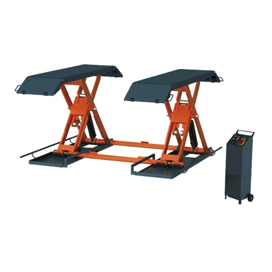
Installation, Operation and Parts Manual EE-MR35 PRODUCT DESCRIPTIONS 3.1 General descriptions This model is designed for mobile use with a maximum lifting height of 1000mm. It is driven by an electro-hydraulic system. The gear pump delivers hydraulic oil to oil cylinders and pushes upwards pistons to raise the platforms. In the process of rising, the mechanical locking unit ensures no unexpected fall caused by failure of hydraulic system. -
Page 10: Dimensions
Installation, Operation and Parts Manual EE-MR35 3.3 Dimensions... -
Page 11: Safety Device Descriptions
Installation, Operation and Parts Manual EE-MR35 3.4 Safety device descriptions 1. Tip-off protection under the platform 2. Tip-off protection fender 3. Max height limit switch 4. Mechanical safety locking unit 5. Feet protection fender 3.5 Technical data Rated capacity 3500KG... -
Page 12: Installation Instructions
Installation, Operation and Parts Manual EE-MR35 INSTALLATION INSTRUCTIONS 4.1 Preparations before installation 4.1.1 Space requirements. Refer to 3.3 for the dimensions of the lift. There must also be a clearance of at least 1 meter between the lifting platform and fixed elements (e.g. -
Page 13: Installation Attentions
Installation, Operation and Parts Manual EE-MR35 4.1.5 Checking parts Unfold the package and check if any parts missed as per the following list. Do not hesitate to contact us in case any parts missed, but if you do not contact us and insist installing upon the lack of some parts, we as well as our dealers will not bear any responsibility for this and will charge for any parts subsequently demanded by the buyer. - Page 14 Installation, Operation and Parts Manual EE-MR35 Step 5: Connect oil hoses. Refer to Annex 3. Connect the fitting of oil hose and its tie-in on the hydraulic block firmly. Attention: Do not contaminate the hydraulic components during the connection. Step 6: Connect electrical system.
-
Page 15: Items To Be Checked After Installation
Installation, Operation and Parts Manual EE-MR35 4.4 Items to be checked after installation. Check items Rising speed ≥20mm/s; √ √ Noise with rated load ≤75db; √ Grounding resistance: not bigger than 4Ω; √ Mechanical locks are robust and synchronized when running with rated load ;... -
Page 16: Flow Chart For Operation
Installation, Operation and Parts Manual EE-MR35 5.3 Flow chart for operation Start Start Turn on the power switch Turn on the power switch Push the DOWN button Push the UP button The lift is lowered The lift is raised 5.4 Operation instructions The lift must be only used in a static position for lifting and lowering vehicles. -
Page 17: Install The Optional Mobile Kit To Move The Lift
Installation, Operation and Parts Manual EE-MR35 5.5 Install the optional mobile kit to move the lift DO NOT attempt to move the lift when it is loaded. 1. Raise the platform about 500mm above the floor and fix the mobile kit as indicated in the below fig. -
Page 18: Emergency Lowering
Installation, Operation and Parts Manual EE-MR35 5.6 Emergency lowering Emergency situation: 1. Electricity power failure; 2.failure on equipment itself. Suitable condition: Compressed air is available. Normally, in case of sudden electricity power failure, the compressed air remained in the air compressor’s tank can still make the pneumatic system of the lift work. -
Page 19: Trouble Shooting
Installation, Operation and Parts Manual EE-MR35 TROUBLE SHOOTING ATTENTION: If the trouble could not be fixed by yourself, please do not hesitate to contact us for help .We will offer our service at the earliest time we can. By the way, your troubles will be judged and solved much faster if you could provide us more details or pictures of the trouble. -
Page 20: Maintenance
Installation, Operation and Parts Manual EE-MR35 MAINTENANCE Easy and low cost routine maintenance can ensure the lift work normally and safely. Follow the below routine maintenance schedule with reference to the actual working condition and frequency of your lift. Lubricate with No.1 lithium base grease. - Page 21 Installation, Operation and Parts Manual EE-MR35 Components Methods Period Every month Locking screw Inspect to ensure the screws are well fastened. Joint shafts Add grease into the oil cups. Every 3 months Add grease onto the running tracks to ensure Sliders smooth running.
-
Page 22: Annex 1, Floor Plan For Fixed Installation
Installation, Operation and Parts Manual EE-MR35 Annex 1, Floor plan for fixed installation Indoor installation only. There must also be a clearance of at least 1 meter between the lifting platform and fixed elements (e.g. wall) in all lifting positions. -
Page 23: Annex 2, Electrical Diagrams And Parts List
Installation, Operation and Parts Manual EE-MR35 Annex 2, Electrical diagrams and parts list (Note: For the specific requirements on voltage, the actual voltage of your lift may differ with the following diagram) - Page 24 Installation, Operation and Parts Manual EE-MR35...
- Page 25 Installation, Operation and Parts Manual EE-MR35 NOTE: There’s no internal wire connected with terminal 12. The two wires which comes from SQ2 and SQ3 and marked with NO.12 share the same termial 12.
- Page 26 Installation, Operation and Parts Manual EE-MR35 Pos. CODE Name Specification 320101004 Transformer-380V-3Ph JBK3-40VA 380V-24V 320101001 Transformer-220V-1Ph JBK3-40VA 220-24V 320101005 Transformer-400V-3Ph JBK3-40VA 400V-24V 320101002 Transformer-230V-1Ph JBK3-40VA 230V-24V 320101006 Transformer-415V-3Ph JBK3-40VA 415V-24V 320101003 Transformer-240V-1Ph JBK3-40VA 240V-24V Motor 2.2KW SQ1,SQ2,SQ3 320301011 Limit switch...
-
Page 27: Annex 3, Hydraulic Diagrams And Parts List
Installation, Operation and Parts Manual EE-MR35 Annex 3, Hydraulic diagrams and parts list 1.oil tank 2.oil sucking filter 3.gear pump 4.coupling 5.motor 6.hydraulic block 7.cushion valve 8.overflow valve 9.single way valve 10.solenoid unloading valve 11.throttle valve 12.oil tank cover 13.hose connector (single way throttle valve included ) 14.cylinder... - Page 28 Installation, Operation and Parts Manual EE-MR35 Pos. CODE Name Specification Hydraulic power unit 2.2KW Rubber oil hose Φ6,L=3350mm, 624001862 Rubber oil hose Φ6,L=4770mm 624001878 Oil cylinder connector CJ-A12-B5-C10 410281130 Composite washer 207103019 MR35 oil cylinder MR35-A15-B1 615050001 MR35 oil cylinder...
- Page 29 Installation, Operation and Parts Manual EE-MR35...
- Page 30 Installation, Operation and Parts Manual EE-MR35 Pos. CODE Name Specification 330405014 6L plastic oil tank 330101005 Hydraulic block YF-2D 330308006 Solenoid unloading valve DHF06-220H/DC24 330304001 Overflow valve EYF-C 330302001 Single way valve DYF-C 330305002 Throttle valve TC-VF 207103019 Composite washer...
-
Page 31: Annex 4, Pneumatic Diagram And Parts List
Installation, Operation and Parts Manual EE-MR35 Annex 4, Pneumatic diagram and parts list Pos. CODE Name Specification 321004006 AFC Pneumatic binary combination AFC2000-M 310101015 Pneumatic connector KLC8-02 310201002 Silencer SLM02 R1/4 (M12) 310401001 Pneumatic directional valve 3V210-08 DC24V 310101017 Pneumatic connector... -
Page 32: Annex 5, Mechanical Exploded Drawings And Parts List
Installation, Operation and Parts Manual EE-MR35 Annex 5, Mechanical exploded drawings and parts list Pos. CODE Name Specification 614050010B Welded base frame assembly A MR35-A01-B01 614050011B Welded base frame assembly B MR35-A02-B01 614018018B Welded safety bar NORDIC-MR30-A26 410180013 U block... - Page 33 Installation, Operation and Parts Manual EE-MR35 Pos. CODE Name Specification 614050001B Slave arm MR35-A03-B01 614050002B Drive arm MR35-A03-B02 614050005 Start plate MR35-A08-B01 614050009 Left-side mechanical lock MR35-A09-B01 614050008 Right-side mechanical lock MR35-A09-B01_ 205101097 Bearing 2515-SF-1X 205101010 Bearing 2525-SF-1 205101018 Bearing...
- Page 34 Installation, Operation and Parts Manual EE-MR35 Pos. CODE Name Specification 410500101 X shaft MR35-A03-B03 410500111 UP rolling wheel MR35-A03-B04 410500281 Shaft of up rolling wheel MR35-A03-B05 410500241 Cylinder shaft of start plate MR35-A08-B02 410500271 Start rolling wheel MR35-A08-B03 310101024 Quick pneumatic connector KLC6-01 Pos.
- Page 35 MR30-A25-B1 615018006 Mobile kit Assembly All information in this manual is believed to be correct at time of publication. EAE reserves the right to amend and alter technical data and composition without prior notice. Please confirm at time of ordering.
Need help?
Do you have a question about the EE-MR35 and is the answer not in the manual?
Questions and answers