Table of Contents
Advertisement
Quick Links
Advertisement
Table of Contents

Related Manuals for EAE EE-612E


Summary of Contents for EAE EE-612E
- Page 1 Model No. EE-612E Installation, Operation ...
-
Page 2: Important Notes
Installation, Operation and Parts Manual EE-612E IMPORTANT NOTES Before start up, connecting and operating EAE products, it is absolutely essential that the operating instructions/owner’s manual and, in particular the safety instructions are studied carefully. By doing so you can eliminate any uncertainties in handling EAE products and thus associated safety risks up front; something which is in the interest of you own safety and will ultimately help avoid damage to the device, When an EAE product is handed over to another person, not only the operating instructions but also the safety instructions and information on its designated use must be handed over to the person. By using the product you agree the following conditions: Copy right The enclosed instructions are the property of EAE or its supplier, and are protected against duplication and reproduction by copyright laws, international agreements, and other domestic legislation. The reproduction or disclosure of instructions or an extract thereof is prohibited and offenders are liable to prosecution; EAE reserves the right or initiates criminal proceedings and asserts claims for damages in the event of infringements. Warranty The use of non‐approved hardware will result in a modification of our products and thus to the exclusion of any liability or warranty, even if such hardware has been removed again in the interim. It is not permissible to make any changes to our products and these are not only to be used together with genuine accessories and genuine replacement parts. Otherwise any warranty claims will be invalid. Liability The liability of EAE is limit to the amount that the customer has actually paid for this product. This exclusion of liability does not apply to damages caused through willful misconduct or gross negligence on the part of EAE ... -
Page 3: Table Of Contents
Installation, Operation and Parts Manual EE-612E IMPORTANT NOTES ............................ 2 1.1 Operation of lifting platforms ........................ 4 1.2 Checking of the lifting platforms ........................ 4 1.3 Important safety notices .......................... 5 1.4 Warning labels ............................... 6 1.5 Potential safety risks ............................ 7 1.6 Noise level .............................. 8 PACKING, STORAGE AND TRANSPORTATION .................... 9 2.1 The lift was dismantled into the following 5 parts for transportation ............ 9 ... -
Page 4: Operation Of Lifting Platforms
Installation, Operation and Parts Manual EE-612E Annex 2, Wiring schemes and parts list ...................... 36 Annex 3, Exploded drawings and parts list ...................... 40 SAFETY NOTES 1.1 Operation of lifting platforms This lift is specially designed for lifting motor vehicles. Users are not allowed to use it for any other purposes. The applicable national regulations, laws and directives must be observed. Only users aged 18 or above who have been instructed on how to operate the lifting platform and have proven their ability to do so to the owner are to be entrusted with unsupervised operation of lifting platforms. The task of operating the lifting platforms must be granted in writing. Before loading a vehicle onto the lifting platform, users should study the original operation instructions and familiarize themselves with the operating procedures in several trial runs. Lift vehicle within the rated load. Don’t attempt to raise vehicles with excessive weight. Do not try to move the lift when it is being lifted with vehicles. 1.2 Checking of the lifting platforms Checks are to be based on the following directives and regulations: Basic principles for testing lifting platforms The basic health and safety requirements. ... -
Page 5: Important Safety Notices
Installation, Operation and Parts Manual EE-612E A qualified person is somebody with the training and experience required to possess sufficient knowledge of lifting platforms and who is sufficiently familiar with the pertinent national regulations, accident prevention regulations and generally acknowledged rules of engineering to be able to assess the safe operating condition of lifting platforms. 1.2.3 Exceptional checking Lifting platforms with a lift height of more than 2 meters and lifting platforms intended for use with people standing under the load bearing elements of the load are to be checked by an expert prior or reuse following structural modifications and major repairs to load bearing components. An expert is somebody with the training and experience required to possess specialist knowledge of lifting platforms and who is sufficiently familiar with the pertinent national work safety regulations, accident prevention regulations and generally acknowledged rules of engineering to be able to check and give an expert option on lifting platforms. 1.3 Important safety notices 1.3.1 DO not expose the lift to rain, snow or excessive moisture. 1.3.2 Only use this lift on a surface that is stable, level and dry and not slippery ,and capable of susutaining the load. Do not install the lift on any asphalt surface. 1.3.3 Read and understand all safety warnings before operating the lift. 1.3.4 Do not leave the controls while the lift is still in motion. 1.3.5 Keep hands and feet away from any moving parts. Keep feet clear of the lift when lowering. 1.3.6 Only these properly trained personnel can operate the lift. 1.3.7 Do not wear unfit clothes such as large clothes with flounces, tires, etc, which could be caught by moving parts of the lift. 1.3.8 To prevent evitable incidents, surrounding areas of the lift must be tidy and with nothing unconcerned. 1.3.9 The lift is simply designed to lift the entire body of vehicles, with its maximum weight within the lifting capacity. 1.3.10 Always insure the safety locks are engaged before any attempt to work near or under the vehicle. Never remove safety related components from the lift. Do not use if safety related components are damaged or missing. 1.3.11 Do not rock the vehicle while on the lift or remove any heavy component from vehicle that may cause excessive weight shift. ... -
Page 6: Warning Labels
Installation, Operation and Parts Manual EE-612E c. Lubricate the moving parts with hydraulic oil. WARNING:the warnings ,cautions and instructions discussed in this instruction manual cannot cover all possible conditions and situations that may occur. It must be understood by the operator that common sense and caution are factors which cannot be built into this product, but must be supplied by the operator. Attention: For environment protection, please dispose the disused oil in a proper way. 1.4 Warning labels All safety warning labels are clearly depicted on the lift to ensure that the operator is aware of and avoid the dangers of using the lift in an incorrect manner. The labels must be kept clean and they have to be replaced if detached or damaged. Please read carefully the meaning of each label and memories them for future operation ... -
Page 7: Potential Safety Risks
Installation, Operation and Parts Manual EE-612E 1.5 Potential safety risks 1.5.1 Mains voltage ... -
Page 8: Noise Level
Installation, Operation and Parts Manual EE-612E nsulation damage and other faults may result in accessible components being live Safety measures: Only ever use the power cord provided or a tested power cord. Replace wires with damaged insulation. Do not open the operating unit. 1.5.2 Risk of injury, danger of crushing In the event of excessive vehicle weight, incorrect mounting of the vehicle or on removing heavy object, there is a risk of the vehicle falling off the lifting platform or tipping up. Safety measures: The lifting platform is only ever to be employed for the intended purpose. Carefully study and heed all the information given in Section 1.4. Observe the warning notices for operation. 1.6 Noise level Noise emitted during operating the lift should be less than 70dB. For your health consideration, it is suggested to place a noise detector in your working area. ... -
Page 9: Packing, Storage And Transportation
Installation, Operation and Parts Manual EE-612E PACKING, STORAGE AND TRANSPORTATION Packing, lifting, handling, transporting operations must be performed only by experienced personnel with appropriate knowledge of the lift and after reading this manual. 2.1 The lift was dismantled into the following 5 parts for transportation Name Packed by Dimension(mm) Weight(KG) Quantity Post Packing frame with 2600*480*410 400 1 corrugated paper bubbled and bubbled film Base frame Bubbled film 1140*1800*80 150 1 Lifting platform Packing frame and bubbled ... -
Page 10: Product Descriptions
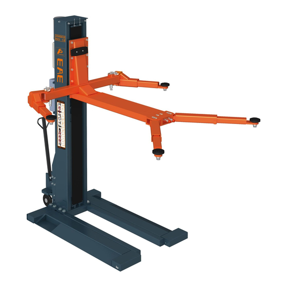
Installation, Operation and Parts Manual EE-612E PRODUCT DESCRIPTIONS 3.1 General descriptions This single post lift is driven by an electro‐hydraulic system. The gear pump delivers hydraulic oil to oil cylinders and pushes upwards its piston. The piston drives the chain to raise the carriage and the lifting arms. During lifting process, the mechanical safety hooking system ensures no slipping in case of hydraulic failure. 3.2 Construction of the lift ... -
Page 11: Dimensions
Installation, Operation and Parts Manual EE-612E 3.3 Dimensions ... - Page 12 Installation, Operation and Parts Manual EE-612E...
-
Page 13: Safety Devices Descriptions
Installation, Operation and Parts Manual EE-612E 3.4 Safety devices descriptions NO. Safety device Function 1 24V control voltage Safe voltage for operators Control the max lifting height (stop rising at height of 1870 mm), and assure 2 Max height limit switch the cylinder run within its max stroke. Assure the lifting platform stop lowering at safety height from the ground by 3 Lowering limit switch initial lowering and trigger the alarm buzzer as a safety warning to avoid ... -
Page 14: Installation Instructions
Installation, Operation and Parts Manual EE-612E Oil Volume 8L INSTALLATION INSTRUCTIONS 4.1 Preparations before installation 4.1.1 Space requirements. Refer to 3.3 for the dimensions of the lift. There must also be a clearance of at least 1 meter between the lifting platform and fixed elements (e.g. wall) in all lifting positions. There must be sufficient space at the ends of the lifting platform for driving vehicles on and off. To stop vehicles colliding with the ceiling, it is advisable to fit an overhead light barrier in low ceiling buildings. 4.1.2 Foundations and connections Attention: electrical system connection must be done by licensed technicians. 2 2 Requirements for power supply cable of the installation site: at least 2.5mm wire core for 3Ph power and 4.0mm wire core for 1Ph power. The user must have the following work performed before erecting the lift. Construction of the foundation following consultation with the manufacturer’s customer service or an authorized service agent. Routing of the wiring to the installation location. The user must provide fuse protection for the connection. Refer also to the corresponding information in the operation instructions. 4.1.3 Foundations preparations ... -
Page 15: Installation Attentions
Installation, Operation and Parts Manual EE-612E S/N Name Spec. Qty Note 1 Portable base frame 612E‐A1 1 a pack 2 Post 612E‐A2 1 a pack 3 Carriage 612E‐A3 1 4 Lifting platform 612E‐A4 1 a pack ... -
Page 16: General Installation Steps
Installation, Operation and Parts Manual EE-612E 4.3 General Installation Steps Step 1: Remove the packaging and take the mechanical and hydraulic assembly to the designated installing place. Step 2: Place the base frame on the expected installation position. Step 3: Move the lifting arms and control box out from the post. Suspend the post by lifting equipment and then dismantle the post from its packing frame. Attention:Please pay special attention not to let the post fall down for it may cause casualty or bring damages to the accessories fixed in the post. ... - Page 17 Installation, Operation and Parts Manual EE-612E Step 4: Fix the post onto to the base frame and the portable kit connector ...
- Page 18 Installation, Operation and Parts Manual EE-612E Step 5: Install the lifting platforms and lifting arms 1. Fix the lifting platform onto the carriage. ...
- Page 19 Installation, Operation and Parts Manual EE-612E 2. Connect lifting arms and the lifting platform. ...
- Page 20 Installation, Operation and Parts Manual EE-612E ...
- Page 21 Installation, Operation and Parts Manual EE-612E Step 6: Fix electromagnets and safety hooks. ...
- Page 22 Installation, Operation and Parts Manual EE-612E Step 8: Connect oil hoses. Connect the oil hose as per the following diagram. Make sure the oil hose connector is clean before making the connection. Short oil hose Step 9: Connect the electrical system. 1. Mount the control box on to the power side post.
- Page 23 Installation, Operation and Parts Manual EE-612E 2. Fix electromagnets 3. Fix limit switches ...
- Page 24 Installation, Operation and Parts Manual EE-612E 4. Connect motor wires, solenoid unloading valve wires and power supply cable. ...
- Page 25 Installation, Operation and Parts Manual EE-612E 3. Connect quick connectors between electromagnets. Step 10: Fix chain protection clothes, electromagnet protectors and lifting trays. Step 11: Fill with hydraulic oil. CLEAN AND FRESH OIL ONLY .DON’T FILL THE TANK COMPLETELY FULL. Lift must be fully lowered before changing or adding hydraulic oil Pour 8 liters HM32 anti‐abrasion hydraulic oil into the oil tank. The level of oil shall reach the tippets volume mark of the tank. Add more oil after running the lift for several cycles until the lift can rise to the maximum lifting height. Note:As running speed of the lift is mainly decided by the viscosity of the hydraulic oil, we suggest using NO.46 hydraulic oil when average temperature of the location is above 18 degree Celsius and using NO.32 hydraulic oil when temperature is below 18 degree Celsius. Change the oil 6 month after initial use and change once per year thereafter. Step 12: Trial running. ...
-
Page 26: Items To Be Checked After Installation
Installation, Operation and Parts Manual EE-612E Get familiar with lift controls by running the lift through a few cycles before loading vehicle on lift.This step is of particular importance for it can check if the oil hose is well connected. The connection is qualified when there is no abnormal sound or leakage after having been tested for 5‐6 times. Raise and lower lift several times. The cylinder is self bleeding. After bleeding system, fluid level in power unit reservoir may be down. Add more oil if necessary to raise lift to full height. It is only necessary to add oil to raise lift to full height. 4.4 Items to be checked after installation. Check items 1 ... -
Page 27: Flow Chart For Operation
Installation, Operation and Parts Manual EE-612E our dealers will not bear any responsibility for any consequence resulted thereby. 5.1.4 Operators and other personnel concerned should stand in a safety area during lifting and lowering process. 5.1.5 When runways being raised to the desired height, switch off the power at once to lock the button with a padlock to prevent any wrong operation done by unconcerned people. 5.1.6 Make sure the safety lock of the lift is engaged before start working under the vehicle and no people under the vehicle during lifting and lowering process. 5.2 Flow chart for operation Lowering Raising Start Start Turn on the power switch Turn on the power switch ... -
Page 28: Trouble Shooting
Installation, Operation and Parts Manual EE-612E Pos. Name Function FA Alarm buzzer Safety warning HL Power indicator Show if electricity is connected SB1 UP button Control the rising movement SB2 LOCK button Engage the mechanical lock ... - Page 29 Installation, Operation and Parts Manual EE-612E earliest time we can. By the way, your troubles will be judged and solved much faster if you could provide us more details or pictures of the trouble. TROUBLES CAUSE SOLUTION Abrasion exists on inside surface of the post. Grease the inside of the post. Abnormal noise Trash in the post. Clear the trash The wire connection is loose. Check and make a good connection. Motor does not run and will The motor is blown. Replace it. not rise Connect it or adjust or replace the The limit switch is damaged or the wire connection is loose. limit switch. The motor run reversely. Check the wire connection. Overflow valve is loose or jammed. Clean or adjust it. The gear pump is damaged. Replace it. Motor runs but will not raise ...
-
Page 30: Maintenance
Installation, Operation and Parts Manual EE-612E MAINTENANCE Easy and low cost routine maintenance can ensure the lift work normally and safely. Following are requirements for routine maintenance. You may decide the frequency of routine maintenance by consulting your lift’s working conditions and time. S/N Components Methods Period Push the UP button to raise the lifting arms and check if two ... - Page 31 Installation, Operation and Parts Manual EE-612E S/N Components Methods Period Lubricate the chain with NO.1 lithium based grease .Change the Every 3 10 Chain and its pins chains every 3 years or if any cracks occurred to the pin of the months chain. Check with torque spanner. For M18 bolt ,the torque is no less Every 3 11 Expansion bolts than 80N.m. months Running the lift for several cycles with and without rated load. The Every 3 12 Lift lift can run steadily and smoothly with no abnormal noise. months Change the oil 6 months after initial use and once per year 13 Hydraulic oil thereafter. Inspect the hydraulic oil and change the oil if the oil ...
-
Page 32: Annex 1, Hydraulic Schemes And Parts List
Installation, Operation and Parts Manual EE-612E Annex 1, Hydraulic schemes and parts list 1. Drive oil cylinder 3. Solenoid unloading valve 4. Throttle valve 5. Motor 6. Coupling 7. Gear pump 8. Single –way valve 9. Over‐flow valve 10. Anti‐surge valve 11. Cushion valve 12. Emergency unloading valve ... - Page 33 Installation, Operation and Parts Manual EE-612E POS. Code Name Specification Qty 1 Hydraulic power unit 2.2kW 1 2 624001042B φ8 Rubber oil hose L=400mm 1 3 615022014 612 right angle connector 612E‐A8 1 4 615022013 Long oil hose (2050mm) 612E‐A12 1 5 615015003 612 composite connector 6255E‐A7‐B7 1 6 ...
- Page 34 Installation, Operation and Parts Manual EE-612E POS. Code Name Specification Qty 1 330405010 oil tank 8L 4 2 330101069C hydraulic block with manual pump YF‐2D 4 ...
- Page 35 Installation, Operation and Parts Manual EE-612E POS. Code Name Specification Qty 3 330308006 solenoid unloading valve DHF06‐220H/DC24 3 4 330304001 over flow valve EYF‐C 3 5 330302001 single way valve DYF‐C 1 6 330305002 throttle valve TC‐VF 1 7 207103019 composite seal ring M14 ...
- Page 36 Installation, Operation and Parts Manual EE-612E Annex2, Wiring schemes and parts list ...
- Page 37 Installation, Operation and Parts Manual EE-612E ...
- Page 38 Installation, Operation and Parts Manual EE-612E...
- Page 39 Installation, Operation and Parts Manual EE-612E POS. Code Name Specification Qty T 320101016 Transformer ‐380V JBK3‐63VA 380V‐24V 1 320101011 Transformer ‐220V JBK3‐63VA 220V‐24V 1 320101017 Transformer ‐400V JBK3‐63VA 400V‐24V 1 M 320201004 Motor 380V‐2.2KW ‐3PH‐50HZ‐2p 1 Motor 320201001 220V‐2.2KW ‐1PH‐50HZ‐2p 1 Motor 320201005 400V‐2.2KW ‐3PH‐50HZ‐2P ...
- Page 40 Installation, Operation and Parts Manual EE-612E Annex3, Exploded drawings and parts list POS. Code Name Specification Qty 1 614022022C Portable base frame 612E‐A1‐B1 1 2 420220060 Nylon wheel 612E‐A1‐B3‐C1 2 3 205202003 Bearing GB/T276‐1994(6205‐2Z) 4 4 410222471 Wheel spacer 612E‐A1‐B4 4 ...
- Page 41 Installation, Operation and Parts Manual EE-612E POS. Code Name Specification Qty 7 410222533 Top connection plate 612E‐A2‐B3 1 8 204201006 Spring washer M12 13 ...
- Page 42 Installation, Operation and Parts Manual EE-612E POS. Code Name Specification Qty 9 204101007 Flat washer M12 13 10 202109085 Hex socket cylinder head screw M12*30 13 11 202101008 Cross socket cap head screw M4*10 4 12 320301011 Limit switch TZ‐8108 TZ8108 1 13 202103007 Cross socket cap head screw M4*25 M4*25 4 ...
- Page 43 Installation, Operation and Parts Manual EE-612E POS. Code Name Specification Qty 38 204101009 M16 flat washer M16 10 39 204201010 M16 spring washer M16 10 40 201102059 Hex head full swivel screw M16*45 10 41 612022008 Pulling rod assembly 612E‐A5‐B25 2 42 206102008 Elastic pin 5x50 ...
- Page 44 Installation, Operation and Parts Manual EE-612E POS. Code Name Specification Qty 46 410150911 Semi‐gear 6255E‐A4‐B4 2 47 204301013 Circle D38 2 Basic Arm (right) 48 614022024C 612E‐A4‐B4‐C1 1 49 614022021B First stage of the rear lifting arm 612E‐A4‐B4‐C2 2 50 420130060 Protective rubber pad 6255E‐A3‐B3 ...
- Page 45 Installation, Operation and Parts Manual EE-612E POS. Code Name Specification Qty 65 202109017 Hex socket cylinder head screw M6*8 M6*8 2 66 410130081 Retaining plate 6255E‐A7‐B6 1 67 204301009 Circlip D25 D25 2 68 410010101 Chain wheel shaft 6254E‐A4‐B3 1 69 410220071B 612 chain wheel 612FE‐A6‐B2 1 ...
- Page 46 Installation, Operation and Parts Manual EE-612E POS. Code Name Specification Qty 76 410222591 Connection shaft 612E‐A9 1 77 204301005 M16 circlip M16 2 78 615022001 612 portable kit 612E‐A8 1 79 614022012B top plate 612E‐A5 1 80 204101004 flat washer D6 M6 ...
- Page 47 Installation, Operation and Parts Manual EE-612E...
Need help?
Do you have a question about the EE-612E and is the answer not in the manual?
Questions and answers
Do you have one of these lifts in the Meadville area or have sold one in the Meadville PA area I could see?