Table of Contents
Advertisement
Quick Links
Advertisement
Table of Contents

Related Manuals for EAE EE-6604BWF


Summary of Contents for EAE EE-6604BWF
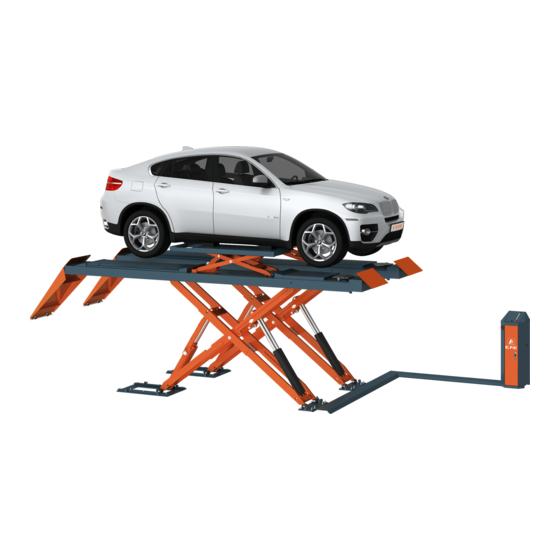
- Page 1 Model No. EE-6604BWF Installation, Operation Long platform scissor lift and Parts Manual Low Profile With synchronization protection Lifting Capacity 4000KG Distributed by Please read this entire manual carefully and completely before installation or operation of the lift. 03/11/2021...
-
Page 2: Important Notes
Liability The liability of EAE is limit to the amount that the customer has actually paid for this product. This exclusion of liability does not apply to damages caused through willful misconduct or gross negligence on the part of EAE. -
Page 3: Table Of Contents
Installation, Operation and Parts Manual EE-6604BWF IMPORTANT NOTES ................................2 SAFETY NOTES ..................................4 1.1 Operation of lifting platforms ............................4 1.2 Checking of the lifting platforms ..........................4 1.3 Important safety notices .............................. 5 1.4 Warning labels ................................6 1.5 Potential safety risks .............................. -
Page 4: Safety Notes
Installation, Operation and Parts Manual EE-6604BWF SAFETY NOTES 1.1 Operation of lifting platforms This lift is specially designed for lifting motor vehicles. Users are not allowed to use it for any other purposes. The applicable national regulations, laws and directives must be observed. -
Page 5: Important Safety Notices
Installation, Operation and Parts Manual EE-6604BWF 1.3 Important safety notices 1.3.1 Recommend for indoor use only. DO not expose the lift to rain, snow or excessive moisture. 1.3.2 Only use this lift on a surface that is stable, level and dry and not slippery, and capable of sustaining the load. Do not install the lift on any asphalt surface. -
Page 6: Warning Labels
Installation, Operation and Parts Manual EE-6604BWF 1.4 Warning labels All safety warning labels are clearly depicted on the lift to ensure that the operator is aware of and avoid the dangers of using the lift in an incorrect manner. The labels must be kept clean and they have to be replaced if detached or... -
Page 7: Potential Safety Risks
Installation, Operation and Parts Manual EE-6604BWF 1.5 Potential safety risks 1.5.1 Mains voltage nsulation damage and other faults may result in accessible components being live Safety measures: Only ever use the power cord provided or a tested power cord. -
Page 8: Packing, Storage And Transportation
Installation, Operation and Parts Manual EE-6604BWF PACKING, STORAGE AND TRANSPORTATION Packing, lifting, handling, transporting operations must be performed only by experienced personnel with appropriate knowledge of the lift and after reading this manual. 2.1 The lift was dismantled into 3 parts for transportation... -
Page 9: Product Descriptions
Installation, Operation and Parts Manual EE-6604BWF PRODUCT DESCRIPTIONS 3.1 General descriptions This is wheel support vehicle lift with auxiliary wheel free lifting device. It is preferably for surface mounting and is mainly composed by lifting platforms, base plates, oil cylinders and a set of operation unit. The gear pump works to make oil in the pump push upwards the pistons of oil cylinders. -
Page 10: Dimensions
Installation, Operation and Parts Manual EE-6604BWF 3.3 Dimensions... -
Page 11: Safety Device Descriptions
Installation, Operation and Parts Manual EE-6604BWF 3.4 Safety device descriptions Safety device Function Restrictive valve Slow down descending speed in case of leaked hydraulic system. Protect the lifting platform from falling down in case of failed Mechanical locking unit hydraulic system. -
Page 12: Technical Data
Installation, Operation and Parts Manual EE-6604BWF 3.5 Technical data Rated capacity(kg) 4000 Full raised height (mm) 1900 Full lowered height (mm) Full raised time (with rated load) Approx.60s Full lowered time (with rated load) Approx. 55s Hydraulic working pressure ( MPa ) Approx.23... - Page 13 Installation, Operation and Parts Manual EE-6604BWF 4.1.4 Tools and equipment needed for installation Tool Description Specification Electrical drill With D16 and D18 drill bit. Open spanner D17-19mm Adjustable spanner bigger than D30mm Cross socket screw driver Quick spanner handle adapter/ Ratchet...
-
Page 14: Installation Attentions
Installation, Operation and Parts Manual EE-6604BWF 4.2 Installation attentions 4.2.1 Joints of oil hose and wiring must be firmly connected in order to avoid leakage of oil hose and looseness of electrical wires. 4.2.2 All bolts should be firmly screwed up. - Page 15 Installation, Operation and Parts Manual EE-6604BWF Connect the wire connectors for rising and lowering limit switches Connect the power supply cable to external electricity supply. (For three phase power supply, if the lift doesn't raise and the motor may turn in the wrong direction, in such event, interchange wires U, V in the control cabinet).
- Page 16 Installation, Operation and Parts Manual EE-6604BWF 2) Push the UP button to raise the platforms to the max height and then lower to the minimum height. Repeat this for 3 cycles. Pay attention to push the UP button very slightly and slowly when the platforms almost reach to the max height. After that, engage the mechanical safety locks and push DOWN I and DOWN II to completely lower the platforms.
-
Page 17: Items To Be Checked After Installation
Installation, Operation and Parts Manual EE-6604BWF ⑤ Impact and drive anchoring bolt into hole until nut and washer contact base. ⑥ Tighten the nut with torque wrench to 80Nm. Step 8: Fix oil hose protection covers. 4.4 Items to be checked after installation. -
Page 18: Operation Instructions
Installation, Operation and Parts Manual EE-6604BWF OPERATION INSTRUCTIONS 5.1 Precautions 5.1.1 Read and digest the complete operation instructions before operating the lift. 5.1.2 Only authorized persons are permitted to operate the lift. 5.1.3 Do not try to raise the vehicle with excessive length or width. -
Page 19: Flow Chart For Operation
Installation, Operation and Parts Manual EE-6604BWF 5.3 Flow chart for operation Raising Lowering Turn on the power switch Turn on the power switch Push UP button Push DOWN I button The platforms rise to release Motor drives the gear pump work... - Page 20 Installation, Operation and Parts Manual EE-6604BWF 2. Push “DOWN II” button to continue lowering the platforms. Meanwhile the buzz alarms. Use the wheel free jack. Lifting capacity: 4000kg Raise the wheel free jack 1. Turn the optional switch on the control panel to “wheel free jack”.
-
Page 21: Trouble Shooting
Installation, Operation and Parts Manual EE-6604BWF TROUBLE SHOOTING ATTENTION: If the trouble could not be fixed by yourself, do not hesitate to contact the distributor or manufacturer for help. We will offer our service at the earliest time we can. Meanwhile the troubles will be judged and solved much faster if more details or pictures of the trouble are provided. -
Page 22: Maintenance
Installation, Operation and Parts Manual EE-6604BWF MAINTENANCE Easy and low cost routine maintenance can ensure the lift work normally and safely. Follow the below routine maintenance schedule with reference to the actual working condition and frequency of your lift. Lubricate with No.1 lithium base grease. - Page 23 Installation, Operation and Parts Manual EE-6604BWF Components Methods Period Padding plate for the start roller Check its tightness and add grease. Every 1 month Open the control unit, inspect the wire terminals and Terminals in the control unit Every 3 months screw firmly if any terminals become loose.
-
Page 24: Annex 1, Floor Plan
Installation, Operation and Parts Manual EE-6604BWF Annex 1, Floor Plan Requirements: ① Indoor installation only. There must be a clearance of at least 1 meter between the lifting platform and fixed elements (e.g. wall) in all lifting positions. There must also be sufficient space for driving vehicles on and off. - Page 25 Installation, Operation and Parts Manual EE-6604BWF Floor Plan for Recessed Mounting In case drain pipes are not available, it is advised to reserve a water collecting pit.
-
Page 26: Annex 2, Electrical Schemes And Parts List
Installation, Operation and Parts Manual EE-6604BWF Annex 2, Electrical schemes and parts list... - Page 27 Installation, Operation and Parts Manual EE-6604BWF...
- Page 28 Installation, Operation and Parts Manual EE-6604BWF...
- Page 29 Installation, Operation and Parts Manual EE-6604BWF SQ1: Max height limit switch of the main lift SQ1: Max height limit switch of the wheel-free lift SQ3: Safe descent limit switch SQ4: Infrared sensor switch YA3: Pneumatic solenoid valve YV1: Solenoid unloading valve...
- Page 30 Installation, Operation and Parts Manual EE-6604BWF POS. Code Description 320101127 Transformer (220V/230V/240V) 320101128 Transformer (380V/400V/415V) 320102005 Transformer (dual 400V230V-24V) Motor 320301003 Limit switch 320301011 Limit switch 320302002 Proximity switch 320306025 Infrared sensor switch 320303018 Selection switch 320303020 Selection switch 320303019...
-
Page 31: Annex 3, Hydraulic Schemes And Parts List
Installation, Operation and Parts Manual EE-6604BWF Annex 3, Hydraulic schemes and parts list 1. Oil tank 2.oil sucking filter 3.gear pump 4.coupling 5.motor 6. Composite hydraulic block 7.cushoin valve 8.overflow valve 9.single way valve 10. Solenoid unloading valve 11.flow control valve 12. Oil tank cover 13.Leveling valve... - Page 32 Installation, Operation and Parts Manual EE-6604BWF POS. Code Description Specification Power unit 3.5 KW 615025004B Main cylinder of the main lift 6604B-A4-B1 615025017B Secondary cylinder of the main lift 6604B-A4-B2 615025012 Main cylinder of the secondary lift 6604B-A11-B1 410210011 Right angled connector...
- Page 33 Installation, Operation and Parts Manual EE-6604BWF POS. Code Description Specification 624001045 Rubber oil hose L=530 624001845 Rubber oil hose L=570 624001260 Rubber oil hose L=3800 410210181 Three way connector 6603B-A9-B7 624001815 Rubber oil hose L=1700 410250271 Four way connector 6604B-A29...
- Page 34 Installation, Operation and Parts Manual EE-6604BWF POS. Code Description Specification 330405027 Steel oil tank 330101044 Composite hydraulic block 6603GN-E 330201014G Gear pump assembly (3.5kW) CBK-F225/CBK-2.5F 320201308B Gear pump assembly (2.2kW) CBK-F216-G 330404001 Coupling YL-A 320203001 Motor 380V-3.5KW -3PH-50HZ-2P Motor 320203005 400V/3.5KW -3PH-50HZ-2P...
-
Page 35: Annex 4, Pneumatic Scheme And Parts List
Installation, Operation and Parts Manual EE-6604BWF Annex 4, Pneumatic scheme and parts list POS. Code Description Specification 321004006 AFC Air filter combination AFC2000 310102015 Quick bending air hose connector KLL8-02 123010101 Air hose 310201002 Silencer SLM02 R1/4 (M12) 310401001 Pneumatic solenoid valve... -
Page 36: Annex 5, Mechanically Exploded Drawings And Parts List
Installation, Operation and Parts Manual EE-6604BWF Annex 5, Mechanically exploded drawings and parts list Pos. Code Description Specification 615025304 48L Main platform 6604V2-A4 410254483 Oil hose protective cover A 6604V2-A13 410254493 Oil hose protective cover B 6604V2-A14 410254503 Oil hose protective cover C... - Page 37 Installation, Operation and Parts Manual EE-6604BWF POS. Code Description Specification 612019504 Shaft of the support holder 65012-A1-B5 614025056 Base A 6604V2-A1-B1 410254270 Bracket for limit switch 6604V2-A1-B2 410250013 Plate for down limit switch 6604V2-A1-B3 320301003 Limit switch D4MC-5020 203101009 Hex nut M16...
- Page 38 Installation, Operation and Parts Manual EE-6604BWF POS. Code Description Specification 614025058 Large base frame 6604V2-A2-B1 410253550 Pad plate for slider 6604V2-A2-B2 410253683B Pressure plate for Base B 6604V2-A2-B3 410255153 Anti-roll plate for Base B 6604V2-A2-B4 201201005 Expansion bolt M16X120 202205002...
- Page 39 Installation, Operation and Parts Manual EE-6604BWF POS. Code Description Specification 420270110 Ball 6435B-A4-B21 410274481 Pull spring 6435B-A4-B31 612019504 Shaft 65012-A1-B5 410250221B Bolt 6604B-A16 420250050B Protective ring 6604B-A17 410250011 Washer 6604B-A1-B5 614025061C Main platform 6604V2-A4-B1 614025062B Slip plate 6604V2-A4-B2 420250010 Nylon sheath...
- Page 40 Installation, Operation and Parts Manual EE-6604BWF POS. Code Description Specification 420040020 Protective ring D20 6254E-A22 420270100B Ball holder 6435B-A4-B20 420270110 Ball 6435B-A4-B21 410274481 Pull spring 6435B-A4-B31 612019504 Shaft 65012-A1-B5 410250221B Bolt 6604B-A16 420250050B Protective sheath 6604B-A17 410250011 Washer 6604B-A1-B5 614025062B...
- Page 41 Installation, Operation and Parts Manual EE-6604BWF POS. Code Description Specification 420680068 Rubber pad DC-20 202109050 Hex socket cylinder head screw M12X20-GB70_1 203101012 Hex nut M20-GB6170 202205005 Hex socket flat head tightening screw M20X140-GB77 203101004 Hex nut M6-GB6170 202110003 Hex socket button head screw...
- Page 42 Installation, Operation and Parts Manual EE-6604BWF POS. Code Description Specification 614025060 Inside support arm 6604V2-A3-B2 410252281 Mid shaft of support bracket 6604V2-A3-B3 410250061 Rotor wheel pad 6604V2-A3-B4 420210060B Padding block 6603B-A5-B6 410252321 DOWN cylinder shaft 6604V2-A3-B6 410251751 Retaining block 6604V2-A3-B7...
- Page 43 Installation, Operation and Parts Manual EE-6604BWF POS. Code Description Specification 205101015 Bearing 2840_SF-2X 205101034 Bearing 4030_SF-2X 420210020 Hex socket button head screw 6603B-A3-B9 614025069B Mechanical lock 6604V2-A5-B3 410252381B Shaft of UP auxiliary cylinder 6604V2-A5-B4 410252391B Shaft of DOWN auxiliary cylinder...
- Page 44 Installation, Operation and Parts Manual EE-6604BWF POS. Code Description Specification 205101015 Bearing 2840 205101054 Bearing 3030_SF-2X 205101026 Bearing 3525_SF-2X 205101034 Bearing 4030_SF-2X 410200111 Spacer 6503-A3-B4 615025004B Main oil cylinder 6604V2-A5-B1 615025017B Secondary oil cylinder 6604V2-A5B-B1 614025045 Start plate 6604V2-A6-B1 410252401...
- Page 45 Installation, Operation and Parts Manual EE-6604BWF POS. Code Description Specification 205101012 Bearing 2530_SF-1X 205101094 Bearing 2540_SF-2X 205101025 Bearing 3058_SF-2X 614027270B Inside connection rod of the secondary lift 6435BWF-C05 410276701 DOWN holder of secondary lift 6435BWF-C03-20 410276711B UP and DOWN wheel...
- Page 46 Installation, Operation and Parts Manual EE-6604BWF POS. Code Description Specification 205101023 Bearing 3050_SF-1X 205101025 Bearing 3058_SF-2X 410212090 Three way oil cylinder connector (small) 6603B-A3-B8 615025012 Drive cylinder of the jack 6604V2-A8-B1 410210011 Right angle connector EEB-WJT-002 POS. Code Description Specification...
Need help?
Do you have a question about the EE-6604BWF and is the answer not in the manual?
Questions and answers