Table of Contents
Advertisement
Advertisement
Table of Contents

Subscribe to Our Youtube Channel
Related Manuals for EAE EE-MR30


Summary of Contents for EAE EE-MR30
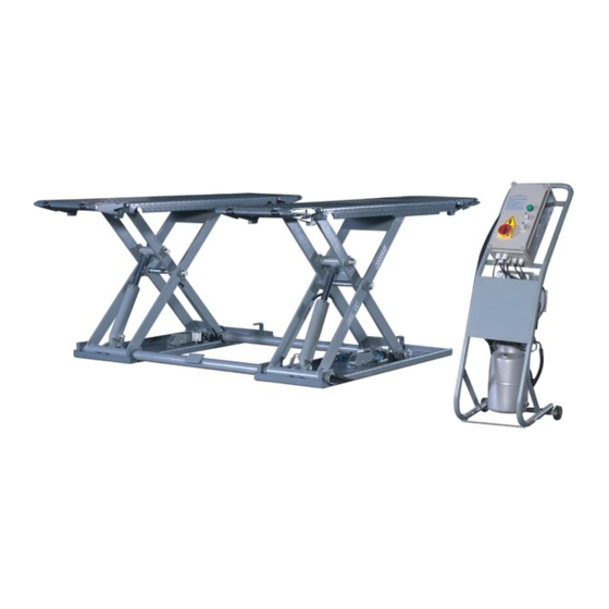
- Page 1 Model No. EE-MR30 Installation, Operation Short Platform Scissor Lift and Parts Manual Mid Rise Electrical Release Lifting Capacity, 3000KG Distributed by Please read this entire manual carefully and completely before installation or operation of the lift. Date: 30.06.2021...
-
Page 2: Important Notes
Liability The liability of EAE is limit to the amount that the customer has actually paid for this product. This exclusion of liability does not apply to damages caused through willful misconduct or gross negligence on the part of EAE. -
Page 3: Table Of Contents
Installation, Operation and Parts Manual EE-MR30 IMPORTANT NOTES .............................. 2 SAFETY NOTES ..............................4 1.1 Operation of lifting platforms ..................................4 1.2 Checking of the lifting platforms ................................4 1.3 Important safety notices ..................................... 5 1.4 Warning labels ......................................6 1.5 Potential safety risks .................................... -
Page 4: Safety Notes
Installation, Operation and Parts Manual EE-MR30 SAFETY NOTES 1.1 Operation of lifting platforms This lift is specially designed for lifting motor vehicles. Users are not allowed to use it for any other purposes. The applicable national regulations, laws and directives must be observed. -
Page 5: Important Safety Notices
Installation, Operation and Parts Manual EE-MR30 familiar with the pertinent national work safety regulations, accident prevention regulations and generally acknowledged rules of engineering to be able to check and give an expert option on lifting platforms. 1.3 Important safety notices 1.3.1 Recommend for indoor use only. -
Page 6: Warning Labels
Installation, Operation and Parts Manual EE-MR30 1.4 Warning labels All safety warning labels are clearly depicted on the lift to ensure that the operator is aware of and avoid the dangers of using the lift in an incorrect manner. The labels must be kept clean and they have to be replaced if detached or damaged. Please read carefully the meaning of... -
Page 7: Potential Safety Risks
Installation, Operation and Parts Manual EE-MR30 1.5 Potential safety risks 1.5.1 Mains voltage nsulation damage and other faults may result in accessible components being live Safety measures: Only ever use the power cord provided or a tested power cord. -
Page 8: Packing, Storage And Transportation
Installation, Operation and Parts Manual EE-MR30 PACKING, STORAGE AND TRANSPORTATION Packing, lifting, handling, transporting operations must be performed only by experienced personnel with appropriate knowledge of the lift and after reading this manual. 2.1 The lift was dismantled into the following 2 parts for transportation... -
Page 9: Product Descriptions
Installation, Operation and Parts Manual EE-MR30 PRODUCT DESCRIPTIONS 3.1 General descriptions This model is chassis supporting vehicle lift for road vehicles. It is designed for mobile use with a maximum lifting height of 1000mm. Being driven by an electro-hydraulic system, the gear pump delivers hydraulic oil to oil cylinders and pushes upwards pistons to raise the lifting platforms. -
Page 10: Dimensions
Installation, Operation and Parts Manual EE-MR30 3.3 Dimensions... -
Page 11: Safety Devices Descriptions
Installation, Operation and Parts Manual EE-MR30 3.4 Safety devices descriptions POS. Descriptions Function 24V control box Safe voltage for users. Anti-surge valve Avoid quick descent in case of hydraulic failure. Mechanical catch Effectively catch the lifting elements in case of hydraulic failure. -
Page 12: Installation Instructions
Installation, Operation and Parts Manual EE-MR30 INSTALLATION INSTRUCTIONS 4.1 Preparations before installation 4.1.1 Space requirements. Refer to 3.3 for the dimensions of the lift. There must also be a clearance of at least 1 meter between the lifting platform and fixed elements (e.g. -
Page 13: Installation Attentions
Installation, Operation and Parts Manual EE-MR30 4.1.5 Checking parts Unfold the package and check if any parts missed as per the following list. Do not hesitate to contact us in case any parts missed, but if you do not contact us and insist installing upon the lack of some parts, we as well as our dealers will not bear any responsibility for this and will charge for any parts subsequently demanded by the buyer. - Page 14 Installation, Operation and Parts Manual EE-MR30 Step 5: Connect electrical system. The electrical system shall only be fixed by qualified electricians. Read and refer to Annex 2. Open the control box and respectively connect electric wires with the terminals in the box.
-
Page 15: Items To Be Checked Before Finishing Installation
Installation, Operation and Parts Manual EE-MR30 Step 8: Install feet protection fenders. 4.4 Items to be checked before finishing installation. Check items Rising speed ≥20mm/s; Noise with rated load ≤75dB(A); Grounding resistance: not bigger than 4Ω; Mechanical locks are robust and synchronized when running with rated load ;... -
Page 16: Operation Instructions
Installation, Operation and Parts Manual EE-MR30 OPERATION INSTRUCTIONS 5.1 Precautions ·ONLY authorized persons are permitted in the lift area. ·Do not try to raise the vehicle with excessive length or width. Otherwise there is risk of vehicle falling from lift. -
Page 17: Flow Chart For Operation
Installation, Operation and Parts Manual EE-MR30 5.3 Flow chart for operation Start Start Turn on the power switch Turn on the power switch Push the UP button Push the DOWN button The lift is lowered The lift is raised 5.4 Operation instructions The lift must be only used in a static position for lifting and lowering vehicles. - Page 18 Installation, Operation and Parts Manual EE-MR30 Special attentions: As the lift is chassis supporting, it is originally designed to lift the max load after a short rise of the supporting platform. For instance, the supporting platform shall at least be raised to a height of 210mm (H≥210mm) in order to lift vehicle with a self-weight of 1800kg.
-
Page 19: Install The Optional Portable Kit To Move The Lift
Installation, Operation and Parts Manual EE-MR30 5.5 Install the optional portable kit to move the lift 1. Raise the platform about 500mm above the floor and fix the portable kit as indicated in the below fig. 2. Lower the platform to the lowest position. -
Page 20: Trouble Shooting
Installation, Operation and Parts Manual EE-MR30 TROUBLE SHOOTING ATTENTION: If the trouble could not be fixed by yourself, please do not hesitate to contact us for help .We will offer our service at the earliest time we can. By the way, your troubles will be judged and solved much faster if you could provide us more details or pictures of the trouble. -
Page 21: Maintenance
Installation, Operation and Parts Manual EE-MR30 MAINTENANCE Easy and low cost routine maintenance can ensure the lift work normally and safely. Follow the below routine maintenance schedule with reference to the actual working condition and frequency of your lift. Lubricate with No.1 lithium base grease. -
Page 22: Annex 1, Floor Plan For Fixed Installation
Installation, Operation and Parts Manual EE-MR30 Components Methods Period Check with torque spanner. The torque should be no less than Self-locking nut Every 3 months 330N.m. Running the lift for several cycles with and without rated load. Whole Lift Every 3 months The lift can run steadily and smoothly with no abnormal noise. -
Page 23: Annex 2, Electrical Diagrams And Parts List
Installation, Operation and Parts Manual EE-MR30 Annex 2, Electrical diagrams and parts list (Note: For the specific requirements on voltage, the actual voltage of your lift may differ with the following diagram) - Page 24 Installation, Operation and Parts Manual EE-MR30...
- Page 25 Installation, Operation and Parts Manual EE-MR30...
- Page 26 Installation, Operation and Parts Manual EE-MR30 Pos. CODE Description 320104010 Transformer 380V400V415V-24V 320104009 Transformer 220V230V240V-24V 320301009 Limit switch SQ2,SQ3 320301011 Limit switch YA1,YA2 330310021 Electromagnet 320304001 Power switch 320401013 Button 320401019 Button 320601005 Relay 320601009 Relay holder 320601018 Relay fixer...
-
Page 27: Annex 3, Hydraulic Diagrams And Parts List
Installation, Operation and Parts Manual EE-MR30 Annex 3, Hydraulic diagrams and parts list 1.oil tank 9.single way valve 2.oil sucking filter 10.solenoid unloading valve 3.gear pump 11.throttle valve 4.coupling 12.oil tank cover 5.motor 13.hose connector (single way throttle valve included ) 6.hydraulic block... - Page 28 Installation, Operation and Parts Manual EE-MR30 Pos. CODE Description Specification Hydraulic power unit 2.2kW 310101008 Connector M14*1.5-G1/4inside cone 624001862 Rubber oil hose L=3350 624001863 Rubber oil hose L=4600 207103025 Composite washer 13.7*20.00*1.50(BS224) 615018002B Left oil cylinder MR30-A15-B1 615018003B Right oil cylinder...
- Page 29 Installation, Operation and Parts Manual EE-MR30 Pos. Code Description Specification 320201201 Motor 230V-2.2KW -1PH-50HZ-2P 320201204 Motor 400V-2.2KW-3PH-50HZ-2P 320201001 Motor 220V-2.2KW-1PH-50HZ-2P 320201003 Motor 240V-2.2KW-1PH-50HZ-2P 320201004 Motor 380V-2.2KW-3PH-50HZ-2P 320201006 Motor 415V-2.2KW-3PH-50HZ-2P 330404006 Coupling 48mm(YBZ-F2.1D4H1/1-03) 203204102 Locking nut FHLM-1/2-20UNF...
- Page 30 Installation, Operation and Parts Manual EE-MR30 Pos. Code Description Specification 330311005 Solenoid valve 24DC(Ketai)(LSV-08-2NCP-M-2H) 330302008 Non-return valve YBZ-E2D3I1/1-03 330105005 Valve holder LBZ-T2BK-13 207103019 Composite washer 310101008 Connector M14*1.5-G1/4 inside cone 210101014 Fitting Z3/8 201101100 Bolt M6*50(NLJLD) 207101098 Type O seal ring 109*5.3...
-
Page 31: Annex 4, Mechanically Exploded Drawings And Parts List
Installation, Operation and Parts Manual EE-MR30 Annex 4, Mechanically exploded drawings and parts list Pos. CODE Description Specification 614901311 Welded base frame assembly (left) MR30V2-A1 614901312 Welded base frame assembly (right) MR30V2-A2 614018002 Feet protection fender MR30-A1-B7 614018018B Connection bar... - Page 32 Installation, Operation and Parts Manual EE-MR30...
- Page 33 Installation, Operation and Parts Manual EE-MR30 Pos. CODE Description Specification 614018066 Slave arm assembly MR30-A03-B01 614018067 Driven arm assembly MR30-A03-B02 615018002B Oil cylinder (left) MR30-A15-B1 615018003B Oil cylinder (right) MR30-A15-B2 410281130 Oil cylinder connector CJ-A12-B5-C10 207103025 Composite washer 13.7*20.00*1.50(BS224) 410180031C...
- Page 34 Installation, Operation and Parts Manual EE-MR30...
- Page 35 Installation, Operation and Parts Manual EE-MR30 Pos. CODE Description Specification 614018010B Supporting rod MR30-A22-B6 614018009C Ramp A assembly MR30-A22 614018011C Ramp B assembly MR30-A23 410180061 Shaft for the ramp MR30-A22-B4 204301004 Circlip 420180010 Small rolling wheel MR30-A22-B5 614901313 Platform assembly...
Need help?
Do you have a question about the EE-MR30 and is the answer not in the manual?
Questions and answers