Table of Contents
Advertisement
Quick Links
Advertisement
Table of Contents

Related Manuals for EAE EE-6435V2.S


Summary of Contents for EAE EE-6435V2.S
- Page 1 Installation, Operation and Parts Manual Model No. EE-6435V2.S / EE-6435V2.B Four Post Lift Electrical Release Lifting Capacity: 4000KG/5000KG Runway Length: 48L/52L/57L Please read this entire manual carefully and completely before installation or operation of the lift. 2017.08.011 - 540104113...
-
Page 2: Important Notes
Liability The liability of EAE is limit to the amount that the customer has actually paid for this product. This exclusion of liability does not apply to damages caused through willful misconduct or gross negligence on the part of EAE. -
Page 3: Table Of Contents
Installation, Operation and Parts Manual EE-6435V2.S/EE-6435V2.B IMPORTANT NOTES ..............................2 SAFETY NOTES ................................4 1.1 Operation of lifting platforms ..................................... 4 1.2 Checking of the lifting platforms ..................................4 1.3 Important safety notices ..................................... 5 1.4 Safety advices........................................6 1.5 Risks and safety instructions ....................................7 1.6 Noise level ........................................... -
Page 4: Safety Notes
Installation, Operation and Parts Manual EE-6435V2.S/EE-6435V2.B SAFETY NOTES 1.1 Operation of lifting platforms This lift is specially designed for lifting motor vehicles. Users are not allowed to use it for any other purposes. The applicable national regulations, laws and directives must be observed. -
Page 5: Important Safety Notices
Installation, Operation and Parts Manual EE-6435V2.S/EE-6435V2.B 1.3 Important safety notices 1.3.1 Recommend for indoor use only, DO not expose the lift to rain, snow or excessive moisture. 1.3.2 Only use this lift on a surface that is stable, level and dry and not slippery, and capable of sustaining the load. Do not install the lift on any asphalt surface. -
Page 6: Safety Advices
Installation, Operation and Parts Manual EE-6435V2.S/EE-6435V2.B 1.4 Safety advices All safety warning labels are clearly depicted on the lift to ensure that the operator is aware of and avoid the dangers of using the lift in an incorrect manner. The labels must be kept clean and they have to be replaced if detached or damaged. -
Page 7: Risks And Safety Instructions
Installation, Operation and Parts Manual EE-6435V2.S/EE-6435V2.B 1.5 Risks and safety instructions During lift functioning, the operator must remain in the control station as defined in figure 1. The presence of persons beneath the cross-pieces and/or the platforms when they are moving, or the presence of persons inside the danger zone indicated in figure 2 is strictly prohibited. - Page 8 Installation, Operation and Parts Manual EE-6435V2.S/EE-6435V2.B RISK OF CRUSHING (PERSONNEL) When the platforms and the vehicle are lowering personnel are prohibited from entering the area beneath the movable parts of the lift (Fig.4). The lift operator must not start the lift until it has been clearly established that there are no persons in danger zone (Fig 1, 4, 5) (Fig.
-
Page 9: Noise Level
Installation, Operation and Parts Manual EE-6435V2.S/EE-6435V2.B RISK OF SLACKENING OF LIFT CABLES Caused by objects left leaning against the posts or on the platforms. (Fig. 9) (Fig.8) risk of vehicle falling (Fig.9) risk of slackening of lift cables. RISK OF SLIPPING Caused by lubricant contamination of the floor around the lift (Fig. -
Page 10: Packing, Storage And Transportation
Installation, Operation and Parts Manual EE-6435V2.S/EE-6435V2.B PACKING, STORAGE AND TRANSPORTATION Packing, lifting, handling, transporting operations must be performed only by experienced personnel with appropriate knowledge of the lift and after reading this manual. 2.1 The lift was dismantled into the following2 parts for transportation... -
Page 11: Products Descriptions
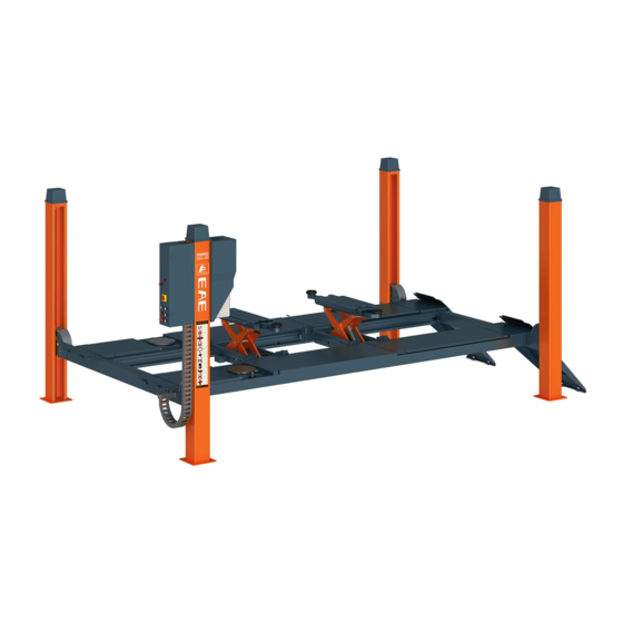
Installation, Operation and Parts Manual EE-6435V2.S/EE-6435V2.B PRODUCTS DESCRIPTIONS 3.1 General descriptions This four post lift is generally composed by four posts, two beams, two platforms, a hydraulic oil cylinder and a set of power unit. It is driven by an electro-hydraulic system. Up and down of platforms is controlled by the to and fro movement of the oil cylinder. -
Page 12: Dimensions
Installation, Operation and Parts Manual EE-6435V2.S/EE-6435V2.B 3.3 Dimensions MODEL B MODEL DATA 4880 5280 5780 5948 6348 6848 4888 5288 5788 4438 4838 5338 1580 1980 2480... - Page 13 Installation, Operation and Parts Manual EE-6435V2.S/EE-6435V2.B MODEL S MODEL DATA 4880 5280 5780 5948 6348 6848 4888 5288 5788 4438 4838 5338...
-
Page 14: Safety Devices Descriptions
Installation, Operation and Parts Manual EE-6435V2.S/EE-6435V2.B 3.4 Safety devices descriptions Safety Device Function Safety rod Ensure mechanical safety in the rising and lowering process and lock the Safety block A lifting platform at expected height. Safety block B Electromagnet Release the mechanical safety lock. -
Page 15: Technical Data
Installation, Operation and Parts Manual EE-6435V2.S/EE-6435V2.B 3.5 Technical data Item Data Power Form Electro-hydraulic Rated capacity of the lifting platform 4000KG(48L/52L), 5000KG(48L/52L/57L) Full rise height of the main lift 1830mm Initial height 180mm Full rise time of the main lift ≤70S... -
Page 16: Installation Instructions
Installation, Operation and Parts Manual EE-6435V2.S/EE-6435V2.B INSTALLATION INSTRUCTIONS 4.1 Preparations before installation 4.1.1 Space requirements. Refer to 3.3 for the dimensions of the lift. There must also be a clearance of at least 0.6 meter between the lifting platform and fixed elements (e.g. - Page 17 Installation, Operation and Parts Manual EE-6435V2.S/EE-6435V2.B 4.1.3 Foundations preparations Indoor installation only. There must also be a clearance of at least 0.6 meter between the lifting platform and fixed elements (e.g. wall) in all lifting positions. There must be sufficient space for driving vehicles on and off.
- Page 18 Installation, Operation and Parts Manual EE-6435V2.S/EE-6435V2.B 4.1.4 Tools and equipment needed for installation Tool name Specification Quantity Electrical drill With D16 and D18 drill bit. Open spanner D17-19mm Adjustable spanner bigger than D30mm Cross socket screw driver Quick spanner handle adapter/ Ratchet...
-
Page 19: Installation Attentions
Installation, Operation and Parts Manual EE-6435V2.S/EE-6435V2.B Name Ramp shaft Expansion bolt Control cabinet Power unit Manual Drive-on ramp 4.2 Installation attentions 4.2.1 Joints of oil hose and wiring must be firmly connected in order to avoid leakage of oil hose and looseness of electrical wires. - Page 20 Installation, Operation and Parts Manual EE-6435V2.S/EE-6435V2.B Step 5: Connect posts and crossbeams. 1. Pull up the safety ladder from the post with its bottom end higher than the height of cross beam. 2. Pull the post to the cross beam as the direction arrow showed in the following drawing. Fasten the top end of safety ladders to the top plate of each post.
- Page 21 Installation, Operation and Parts Manual EE-6435V2.S/EE-6435V2.B Step 6: Fit on 8 nylon sliders and 4 protection covers. 1. Fasten the slider to its holder and then connect the slider holder and the cross beam. 2. Fix protection covers. Step 7: Fix the drive-on ramps.
- Page 22 Installation, Operation and Parts Manual EE-6435V2.S/EE-6435V2.B Secondly, level the platforms after mechanical safety locks are engaged. Raise the platform about 750mm-800mm high and check if the safety blocks in the four posts could be engage synchronously. If not, adjust screw ①to ensure the synchronization.
-
Page 23: Items To Be Checked After Installation
Installation, Operation and Parts Manual EE-6435V2.S/EE-6435V2.B 4.4. Items to be checked after installation Check items Screw torque of expansion bolts : 60-80N•m; Rising speed ≥20mm/s; Noise with rated load ≤75db; Grounding resistance: not bigger than 4Ω; Height difference of the two platform ≤5mm;... -
Page 24: Descriptions Of Control Panel
Installation, Operation and Parts Manual EE-6435V2.S/EE-6435V2.B 5.2 Descriptions of control panel POS. Name Function Alarm buzzer Low height warning Power switch Power on/ off Power indicator Display if electricity is connected UP button Control the rising movement DOWN I button Control the initial lowering movement 1.1 In case the clearance between the platform and... -
Page 25: Operation Instructions
Installation, Operation and Parts Manual EE-6435V2.S/EE-6435V2.B 5.4 Operation instructions The lift must be only used in a static position for lifting and lowering vehicles. Only use this lift on a surface that is stable and capable of sustaining the load. Do not install the lift on any asphalt sur face. -
Page 26: Trouble Shooting
Installation, Operation and Parts Manual EE-6435V2.S/EE-6435V2.B TROUBLE SHOOTING ATTENTION: If the trouble could not be fixed by yourself, please do not hesitate to contact us for help .We will offer our service at the earliest time we can. By the way, your troubles will be judged and solved much faster if you could provide us more details or pictures of the trouble. -
Page 27: Maintenance
Installation, Operation and Parts Manual EE-6435V2.S/EE-6435V2.B MAINTENANCE Easy and low cost routine maintenance can ensure the lift work normally and safely. Following are requirements for routine maintenance. Follow the below routine maintenance schedule with reference to the actual working condition and frequency of your lift. - Page 28 Installation, Operation and Parts Manual EE-6435V2.S/EE-6435V2.B Components Methods Period Push the DOWNI button. Inspect and ensure the runways stop Safety lowering limit switch lowering at safety height (300mm) and then push DOWN II button Every week to have the platform fully lowered.
-
Page 29: Annex 1, Steel Cable Connection
Installation, Operation and Parts Manual EE-6435V2.S/EE-6435V2.B Annex 1, Steel cable connection... -
Page 30: Annex 2, Electrical Schemes And Parts List
Installation, Operation and Parts Manual EE-6435V2.S/EE-6435V2.B Annex 2, Electrical schemes and parts list... - Page 31 Installation, Operation and Parts Manual EE-6435V2.S/EE-6435V2.B...
- Page 32 Installation, Operation and Parts Manual EE-6435V2.S/EE-6435V2.B...
- Page 33 Installation, Operation and Parts Manual EE-6435V2.S/EE-6435V2.B...
- Page 34 Installation, Operation and Parts Manual EE-6435V2.S/EE-6435V2.B Table for PCB Connection Printed Code on CODE for wire Terminal Color Wire terminals the board /Out terminals 0.16.17(Two NO.0 5.6.7 Blue Control box -electromagnet is connected together ) Control box -limit switch of out of level...
- Page 35 Installation, Operation and Parts Manual EE-6435V2.S/EE-6435V2.B POS. CODE Name Specification 320602007 Time relay fixer 320701033 Compact socket P32J3A 320701034 Compact plug P32K3R(P32K3S)(P32K2S) 320801001 Circuit breaker (3Ph) DZ47-63C16/3P Circuit breaker (1Ph) DZ47-63C32/2P 320802001 320803006 Circuit breaker DZ47-63C10/1P 320803007 Circuit breaker DZ47-63C16/1P 320901001 AC contactor(2.2kW)
-
Page 36: Annex 3, Hydraulic Schemes And Parts List
Installation, Operation and Parts Manual EE-6435V2.S/EE-6435V2.B Annex 3, Hydraulic schemes and parts list Oil tank Oil sucking filter Gear pump Coupling Motor Composite hydraulic block Cushion valve Over-flow valve Singe-way valve Solenoid unloading valve Flow-control valve Oil tank cover Main oil cylinder... - Page 37 Installation, Operation and Parts Manual EE-6435V2.S/EE-6435V2.B REMARK Pos. CODE Name Specification Power unit 2.2kW or 3.5kW 624001864 Rubber oil hose L=5750mm 624001867 Rubber oil hose L=6150mm 624001868 Rubber oil hose L=7000mm PU hose DE8,L=4250mm PU hose DE8,L=4650mm PU hose DE8,L=5500mm...
- Page 38 Installation, Operation and Parts Manual EE-6435V2.S/EE-6435V2.B...
- Page 39 Installation, Operation and Parts Manual EE-6435V2.S/EE-6435V2.B CODE Name Specification Pos. 330305002 Throttle valve 330405001 Oil tank Motor 220V-2.2KW -1PH-50HZ-2p 320201001 320201002 Motor 230V-2.2KW -1PH-50HZ-2P 320201003 Motor 240V-2.2KW -1PH-50HZ-2P Motor 380V-2.2KW -3PH-50HZ-2p 320201004 320201005 Motor 400V-2.2KW -3PH-50HZ-2P Motor 415V-2.2KW -3PH-50HZ-2P 320201006 Motor 380V-3.5KW -3PH-50HZ-2P...
-
Page 40: Annex 4, Exploded Drawings And Parts List
Installation, Operation and Parts Manual EE-6435V2.S/EE-6435V2.B Annex 4, Exploded drawings and parts list Pos. CODE Name Specification NOTE Power side post B Secondary post Power side crossbeam Secondary crossbeam Main platform Secondary platform Slip plate 410274513 Front wheel stop plate... - Page 41 Installation, Operation and Parts Manual EE-6435V2.S/EE-6435V2.B Pos. CODE Name Specification NOTE 615027109 Steel cable Φ12,L=12940 48L/2850 615027105 Steel cable 52L/2850 Φ12,L=13340 615027106 Steel cable Φ12,L=13840 57L/2850 615027038B Steel cable Φ12,L=13050 48L/3000 615027037B Steel cable 52L/3000 Φ12,L=13450 615027036 Steel cable Φ12,L=13980...
- Page 42 Installation, Operation and Parts Manual EE-6435V2.S/EE-6435V2.B Pos. CODE Name Specification NOTE 614027703 Power side post 6435B-A1-B3 614027091B Secondary post 6435B-A1-B1-B 612027001B Safety rod 6435B-A1-B2 420270140 Clip of safety rod 6435B-A1-B13 420270090 Post cap 6435B-A1-B11 614027108 Control unit holder 6435B-A1-B4--V2 Control unit...
- Page 43 Installation, Operation and Parts Manual EE-6435V2.S/EE-6435V2.B Pos. CODE Name Specification NOTE 614027611 Power side crossbeam 6435B-A2-B1-48LA--V2 2850 614027613 Power side crossbeam 6435B-A2-B1-48LB--V2 3000 614027612 The opposite crossbeam 6435B-A2-B2-48LA--V2 2850 614027614 The opposite crossbeam 6435B-A2-B2-48LB--V2 3000 410274120 Pulley A 410274120 205101070...
- Page 44 Installation, Operation and Parts Manual EE-6435V2.S/EE-6435V2.B Pos. CODE Name Specification NOTE 410270031B Small pulley 6435B-A3-B5 410270630 Spring 6435B-A3-B22 410270051D Safety block B1 6435B-A3-B7 410270061 Adjustable rod A 6435B-A3-B8 410270660 Spring 6435B-A3-B32 330310007 Electromagnet 6435B-A14 (MQB3-10-20/AC24V) 410270601 Adjustable post 6435B-A3-B33 410270151...
- Page 45 Installation, Operation and Parts Manual EE-6435V2.S/EE-6435V2.B...
- Page 46 Installation, Operation and Parts Manual EE-6435V2.S/EE-6435V2.B Pos. CODE Name Specification NOTE 614027521 Platform A 6435B-A5-B1-57L--V2 57L.50T 614027523 Platform A 6435B-A5-B1-52L--V2 52L.50T 614027525 Platform A 6435B-A5-B1-48L--V2 48L.50T 614027527 Platform A 6435B-A4-B1-52L--V2 52L.40T 614027529 Platform A 6435B-A4-B1-48L--V2 48L.40T 614027522 Platform B 6435B-A5-B2-57L--V2 57L.50T...
- Page 47 Installation, Operation and Parts Manual EE-6435V2.S/EE-6435V2.B Pos. CODE Name Specification NOTE 614027302 Portable box I-184mm 6435B-A4-B4 615027049 400*400 Turntable(optional) 614027248 Slip plate (57L) 6435B-A5-B3-57L 614027258 Slip plate (52L) 6435B-A4-B3-52L 614027318 Slip plate (48L) 6435B-A4-B3-48L 410250221B Bolt 6604B-A16 420210030 Nylon sheath 6603B-A4-B7-C4 6604B-A1-B5 ¢40 L=7...
- Page 48 Installation, Operation and Parts Manual EE-6435V2.S/EE-6435V2.B...
- Page 49 Installation, Operation and Parts Manual EE-6435V2.S/EE-6435V2.B Pos. CODE Name Specification NOTE 614027551 Platform A 6435S-A5-B1-57L--V2 57L.50T 614027553 Platform A 6435S-A5-B1-52L--V2 52L.50T 614027555 Platform A 6435S-A5-B1-48L--V2 48L.50T 614027557 Platform A 6435S-A4-B1-52L--V2 52L.40T 614027559 Platform A 6435S-A4-B1-48L--V2 48L.40T 614027552 Platform B 6435S-A5-B2-57L--V2 57L.50T...
- Page 50 Installation, Operation and Parts Manual EE-6435V2.S/EE-6435V2.B Pos. CODE Name Specification 614027255B Ramp 6435B-A4-B5- 410270091 Shaft III 6435B-A3-B12 206201001 Cotter pin M2.5*30 410270201 Roll wheel shaft 6435B-A4-B5-C8 420270250 Roll wheel 6435BWF-C08-9 204301004 Circlip φ15 (type B) 410274313 Adjustable plate 410274313 202109029...
Need help?
Do you have a question about the EE-6435V2.S and is the answer not in the manual?
Questions and answers