Table of Contents
Advertisement
Quick Links
UM90029
NEVB-MCTRL-100-01-3INV-001-01
Abstract:
This user manual describes Nexperia's motor driver evaluation kit and details its set-up and use. Design
details of the motor controller and 3-phase inverter PCBs are included.
Keywords:
NEVB-MCTRL-100-01-3INV-001-01, BLDC, motor controller, 3 phase, H-bridge, LFPAK56
Rev. 1.0 — 15 April 2024
motor driver evaluation kit
User manual
Advertisement
Chapters
Table of Contents

Related Manuals for Nexperia NEVB-MCTRL-100-01-3INV-001-01


Summary of Contents for Nexperia NEVB-MCTRL-100-01-3INV-001-01
- Page 1 NEVB-MCTRL-100-01-3INV-001-01 motor driver evaluation kit Abstract: This user manual describes Nexperia's motor driver evaluation kit and details its set-up and use. Design details of the motor controller and 3-phase inverter PCBs are included. Keywords: NEVB-MCTRL-100-01-3INV-001-01, BLDC, motor controller, 3 phase, H-bridge, LFPAK56...
-
Page 2: Table Of Contents
Nexperia B.V. 2024. All rights reserved © 3. 3-phase inverter board..........7 For more information, please visit: http://www.nexperia.com For sales office addresses, please send an email to: salesaddresses@nexperia.com 3.1. Power supply and high-side current monitoring... 7 Date of release: 15 April 2024 3.2. Half-bridge MOSFETs..........8 3.3. -
Page 3: Introduction
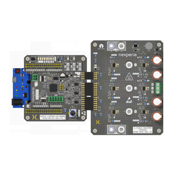
The modular design of the BLDC motor driver kit allows for different motor controllers, gate drivers, MOSFETs and motors to be used. In addition, each board provides convenient test points for power, motor drive, and sensing signals to aid with development and testing with Nexperia’s LFPAK56 MOSFET family. -
Page 4: Motor Evaluation Kit Specifications
UM90029 Nexperia NEVB-MCTRL-100-01-3INV-001-01 motor driver evaluation kit 3-phase inverter board Development board Motor controller board Phase current sense Hall-effect sensors Gate drivers User controls DC/DC MOSFET half-bridges Fault LEDs sense signals VIN current sense jumper BLDC motor to select VIN (12 - 48 V) -
Page 5: Safety Precautions
UM90029 Nexperia NEVB-MCTRL-100-01-3INV-001-01 motor driver evaluation kit 1.2. Safety precautions • Motor Handling: Ensure that the motor is securely clamped down and cannot move unexpectedly during operation. This is crucial to prevent any accidents or damage to the system. Operating Ranges: Verify that the motor's intended operating ranges (voltage, current, speed, •... -
Page 6: Getting Started
UM90029 Nexperia NEVB-MCTRL-100-01-3INV-001-01 motor driver evaluation kit 2. Getting started VDD power VIN1 VIN1 connectors supply select interface 12-48V Fault LED Motor indicators controls External VDD supply header Micro USB input Development board power supply select Hall effects Motor speed... -
Page 7: Phase Inverter Board
UM90029 Nexperia NEVB-MCTRL-100-01-3INV-001-01 motor driver evaluation kit 3. 3-phase inverter board The 3-phase inverter board is the power stage of the motor driver kit, see Fig. 4, it features: • Power supply connections • High-side current monitoring • 3 x half-bridge LFPAK56 MOSFET pairs •... -
Page 8: Half-Bridge Mosfets
The 3-phase inverter board includes four 270 μF aluminum electrolytic capacitors and six 4.7 uF ceramic capacitors for VIN, with additional footprints to accommodate more on the bottom of the board if required. There is also a Nexperia TVS, PTVS60VP1UTP, (D7) which, with a 60 V standoff voltage, provides over-voltage protection. -
Page 9: Table 2. Half-Bridge Mosfet Designations
UM90029 Nexperia NEVB-MCTRL-100-01-3INV-001-01 motor driver evaluation kit MOSFET and a low-side MOSFET, see Fig. 6. The outputs of the half-bridges are referred to as Phase U, Phase V and Phase W, see Table Table 2. Half-bridge MOSFET designations Phase Location... -
Page 10: Interface Connector
UM90029 Nexperia NEVB-MCTRL-100-01-3INV-001-01 motor driver evaluation kit Fig. 7. Motor phase terminal block 3.3. Interface Connector The interface connector (J11 and J12) is the signal interface between the 3-phase inverter board and the controller board, see Fig. 8. As a result, most MOSFET gate, and drain or source connections are used as IOs or monitoring. - Page 11 UM90029 Nexperia NEVB-MCTRL-100-01-3INV-001-01 motor driver evaluation kit Net name Pin number Description PHASE_W Switch node or motor phase voltage of phase W GATE_WB Low side gate voltage for phase W CURRENT Output voltage from high-side current monitor 7, 9 Not used...
-
Page 12: Probing Signals
UM90029 Nexperia NEVB-MCTRL-100-01-3INV-001-01 motor driver evaluation kit 3.4. Probing signals There are test points available to probe most signals on the board which have been designed to allow use with different probe types and tips. By default, they are populated with loop terminal for convenient probing using probes with hook tips, as show in Fig. -
Page 13: Fig. 11. 3-Phase Inverter Board With 2.54 Mm And 5.08 Mm Pin Headers Populated For Test Points
UM90029 Nexperia NEVB-MCTRL-100-01-3INV-001-01 motor driver evaluation kit Fig. 11. 3-phase inverter board with 2.54 mm and 5.08 mm pin headers populated for test points Warning: Test points with the symbol are to be referenced on the board to signals other than common ground. -
Page 14: Motor Controller Board
UM90029 Nexperia NEVB-MCTRL-100-01-3INV-001-01 motor driver evaluation kit 4. Motor controller board The motor controller board connects to the development board and to the 3-phase inverter board, Fig. 12, it features: • DC-to-DC converter to generate VDD • Gate driver for MOSFETs •... -
Page 15: Gate Driver For Mosfets
UM90029 Nexperia NEVB-MCTRL-100-01-3INV-001-01 motor driver evaluation kit Fig. 13. DC-to-DC step-down regulator Note: if VIN is less than 12 V an external supply is required and JP1 should be set to position 2 - 3, so connector J2 is used to supply VDD from an external source, instead of the DC-to-DC converter. -
Page 16: Position Sensor Inputs
UM90029 Nexperia NEVB-MCTRL-100-01-3INV-001-01 motor driver evaluation kit 4.3. Position sensor inputs Fig. 15. Hall-effect sensor input connections The motor controller board can work with different types of position sensors; seeTable • Hall-effect sensors, with 3 output signals • Incremental encoders, with 2 output signals •... -
Page 17: Development Board (Microcontroller) Connections
UM90029 Nexperia NEVB-MCTRL-100-01-3INV-001-01 motor driver evaluation kit 4.4. Development board (microcontroller) connections Fig. 16. Connections to development board (e.g. Leonardo R3 development board) Table 5 lists the power connections (J4) between the motor controller board and the development board (e.g. Leonardo R3 development board). -
Page 18: Table 5. Development Board Power Connector; J4
UM90029 Nexperia NEVB-MCTRL-100-01-3INV-001-01 motor driver evaluation kit Table 5. Development board power connector; J4 Pin name Pin number Description NC_1 This signal is connected to J3[10] and is not used IOREF IOREF is sourced from the development board and is 5... -
Page 19: Table 7. Development Board Fault Status And Mosfet Gate Driver Signal Connector; J7 (Ioh)
UM90029 Nexperia NEVB-MCTRL-100-01-3INV-001-01 motor driver evaluation kit Table 7. Development board fault status and MOSFET gate driver signal connector; J7 (IOH) Net name Pin number Description FAULT_BIT2 FAULT_BIT2 is a digital output on the development board to the MUX PWM_UB... -
Page 20: Table 9. Connection For Alternative Mcu Development Boards (E.g. Nucleo); J3
UM90029 Nexperia NEVB-MCTRL-100-01-3INV-001-01 motor driver evaluation kit Table 9. Connection for alternative MCU development boards (e.g. Nucleo); J3 Net name Pin number Description 1 - 7, 9, 11, 13, 15, No connection 21, 23, 25 - 27, 29, 31, 33... -
Page 21: Interface Signals To The 3-Phase Inverter Board
UM90029 Nexperia NEVB-MCTRL-100-01-3INV-001-01 motor driver evaluation kit Table 10. Connection for alternative MCU development boards (e.g. Nucleo); J9 Net name Pin number Description 1, 2, 4, 6, 8, 10 This connection is not used -14, 16 - 18, 20, 22, 25 - 27, 32, 34,... -
Page 22: Table 11. Interface Connectors; J10 And J11
UM90029 Nexperia NEVB-MCTRL-100-01-3INV-001-01 motor driver evaluation kit Fig. 17. Interface signals to the 3-phase inverter board Table 11. interface connectors; J10 and J11 Net name Pin number Description GATE_UT High-side gate voltage for phase U PHASE_U Switch node or motor phase voltage of phase U... -
Page 23: Back-Emf Zero-Crossing Detection Circuit
UM90029 Nexperia NEVB-MCTRL-100-01-3INV-001-01 motor driver evaluation kit 4.6. Back-EMF zero-crossing detection circuit The BLDC back-EMF zero-crossing detection circuit uses a voltage divider for each phase voltage to step down the motor’s back-EMF, see Fig. 18, which is then fed to a comparator. The reference voltage for each phase comparator is measured by creating a virtual center tap or neutral. -
Page 24: Mux, Fault And Over-Voltage Leds
Fig. 20. MUX, fault LEDs, and over-voltage LEDs Fault bits 1, 2, and 3 are inputs to a Nexperia multiplexer IC (MUX), CBT3251, The multiplexer switches the +5 V supply to activate LEDs, D7 to D13, according to the input bits. These bits... -
Page 25: Default Settings
UM90029 Nexperia NEVB-MCTRL-100-01-3INV-001-01 motor driver evaluation kit Table 12. Fault status LEDs Fault Fault bits Description (b3b2b1) Not connected, not a valid state Over-current (D13) 001 Current warning limit in software has been exceeded by current sense on 3-phase inverter board. If User LEDs... -
Page 26: Default Motor Controls
UM90029 Nexperia NEVB-MCTRL-100-01-3INV-001-01 motor driver evaluation kit Fig. 21. Motor control board; default jumper positions For further details see Section 4.1 Section 4.4. 5.2. Default motor controls There are 4 default controls settings on the motor control board, 3 switches and 1 potentiometer, (see Fig. -
Page 27: Connecting The Bldc Kit
UM90029 Nexperia NEVB-MCTRL-100-01-3INV-001-01 motor driver evaluation kit Fig. 22. Default motor controls and speed control position More information about these controls can be found in Section 4.7. 5.3. Connecting the BLDC kit Fig. 23 shows the motor controller board, Leonardo R3 development board and 3-phase inverter board connected together. -
Page 28: Connecting The 3-Phase Bldc Motor
UM90029 Nexperia NEVB-MCTRL-100-01-3INV-001-01 motor driver evaluation kit Fig. 23. Connecting the BLDC kit boards Table 13. Motor controller to 3-phase inverter board interface connectors Motor controller board 3-phase inverter board Description (plug) (receptacle) J1 (VIN1) J10 (VIN) This is the main power supply from the... -
Page 29: Default Motor Controller Board Voltages
UM90029 Nexperia NEVB-MCTRL-100-01-3INV-001-01 motor driver evaluation kit Fig. 24. Hall sensor and motor phase wire connections 5.5. Default motor controller board voltages Table 14 lists the nominal power supply voltages upon successful power up: Table 14. Default motor controller board voltages... -
Page 30: Bldc Kit Software
UM90029 Nexperia NEVB-MCTRL-100-01-3INV-001-01 motor driver evaluation kit 6. BLDC kit software The firmware provided with this kit allows trapezoidal control of Brushless DC (BLDC) motors using Hall-effect sensors specifically using the Leonardo R3 development board or the ATMEGA 32u4 microcontroller, which is a platform widely recognized under the Arduino Leonardo nomenclature. -
Page 31: Setting Up The Project
UM90029 Nexperia NEVB-MCTRL-100-01-3INV-001-01 motor driver evaluation kit 6.2. Setting up the project 6.2.1. Connecting and selecting the development board This section details the connection of the Leonardo R3 development board and selecting it in the Arduino IDE, Arduino IDE V1 is used. -
Page 32: Default Firmware Configuration
UM90029 Nexperia NEVB-MCTRL-100-01-3INV-001-01 motor driver evaluation kit 6.4. Default firmware configuration The following are some of the default configurations for the most commonly changed parameters used by in the firmware code provided for version NEVC-MCTRL-100-t01-1.0.0: • MOSFET switching frequency: 20,000 Hz •... -
Page 33: Using Remote Mode
UM90029 Nexperia NEVB-MCTRL-100-01-3INV-001-01 motor driver evaluation kit Table 15. Firmware SCPI command set Command Description Parameters Return value Configures the motor enable Boolean (ON or 1 OFF or 0 to disable CONFigure:MOTOr:ENABle state to enable Queries the motor enable None... - Page 34 UM90029 Nexperia NEVB-MCTRL-100-01-3INV-001-01 motor driver evaluation kit • At the bottom right corner of the Serial Monitor, you will find a drop-down menu for setting the baud rate and other parameters. Set them as follows to match the board's configuration: •...
-
Page 35: Customized Operation
4. Review the "ToDo"" section in the motor control firmware and change where applicable, (Note: Nexperia cannot support questions regarding changes to the firmware) The terminal block J4 provides a convenient connection, but screw terminals J1 - J3 can be used for higher current. -
Page 36: Using A Different Motor Algorithm
2. Take note of essential signals, such as gate voltage signals 3. Develop break-out board for new development board Note: Nexperia cannot support questions regarding changes to the firmware 7.3. Using different MOSFETs 1. Review 5 x 6 footprint compatibility with selected MOSFET 2. -
Page 37: Motor Controller Board Schematics
Nexperia UM90029 NEVB-MCTRL-100-01-3INV-001-01 motor driver evaluation kit 8.1. Motor controller board schematics VDD powers the gate drivers, and MCU board. VDD source can be selected between the internal VDD or an external VDD can be used when VIN within 12 - 24V. -
Page 38: Fig. 26. Motor Controller Board Schematic Sheet 2
Nexperia UM90029 NEVB-MCTRL-100-01-3INV-001-01 motor driver evaluation kit J3 and J9 can be used to extend support to other microcontroller boards. Connections to Microcontroller Board (e.g. Arduino™ Leonardo) User Inputs Fig. 26. Motor controller board schematic sheet 2 UM90029 All information provided in this document is subject to legal disclaimers. -
Page 39: Fig. 27. Motor Controller Board Schematic Sheet 3
Nexperia UM90029 NEVB-MCTRL-100-01-3INV-001-01 motor driver evaluation kit Gate Drivers Connections to Inverter Board Gate driver options: MIC4104YM for TTL logic, 9 - 16V supply voltage, 3A source/2A sink MIC4103YM for CMOS logic, 9 - 16V supply voltage, 3A source/2A sink MIC4605-1YM for TTL logic, 5.5 - 16V supply voltage, 1A source/1A sink... -
Page 40: Fig. 28. Motor Controller Board Schematic Sheet 4
Nexperia UM90029 NEVB-MCTRL-100-01-3INV-001-01 motor driver evaluation kit Short R33, R34 and R45 to connect Hall pins to phase voltage sense comparator outputs Hall Inputs Phase Voltage Sense Fig. 28. Motor controller board schematic sheet 4 UM90029 All information provided in this document is subject to legal disclaimers. -
Page 41: Fig. 29. Motor Controller Board Schematic Sheet 5
Nexperia UM90029 NEVB-MCTRL-100-01-3INV-001-01 motor driver evaluation kit Over Voltage LED 8-throw bus switch/multiplexer for fault LEDs Fig. 29. Motor controller board schematic sheet 5 UM90029 All information provided in this document is subject to legal disclaimers. Nexperia B.V. 2024. All rights reserved ©... -
Page 42: 3-Phase Inverter Board Schematics
Nexperia UM90029 NEVB-MCTRL-100-01-3INV-001-01 motor driver evaluation kit 8.2. 3-phase inverter board schematics DC Current Sense and Capacitor Bank Fig. 30. 3-phase inverter board schematic sheet 1 UM90029 All information provided in this document is subject to legal disclaimers. Nexperia B.V. 2024. All rights reserved ©... -
Page 43: Fig. 31. 3-Phase Inverter Board Schematic Sheet 2
Nexperia UM90029 NEVB-MCTRL-100-01-3INV-001-01 motor driver evaluation kit Fig. 31. 3-phase inverter board schematic sheet 2 UM90029 All information provided in this document is subject to legal disclaimers. Nexperia B.V. 2024. All rights reserved © Submit document feedback User manual Rev. 1.0 — 15 April 2024... -
Page 44: Fig. 32. 3-Phase Inverter Board Schematic Sheet 3
Nexperia UM90029 NEVB-MCTRL-100-01-3INV-001-01 motor driver evaluation kit Fig. 32. 3-phase inverter board schematic sheet 3 UM90029 All information provided in this document is subject to legal disclaimers. Nexperia B.V. 2024. All rights reserved © Submit document feedback User manual Rev. 1.0 — 15 April 2024... -
Page 45: Motor Controller Board Pcb Layout
UM90029 Nexperia NEVB-MCTRL-100-01-3INV-001-01 motor driver evaluation kit 8.3. Motor controller board PCB layout Motor controller board PCB characteristics: • Copper layer count: 4 • Board thickness: 1.58 mm • Overall dimensions: 83.7 mm x 88.4 mm • Min track / spacing: 0.20 mm / 0.20 mm •... -
Page 46: Fig. 34. Motor Controller Board Pcb - Inner Layer 1
UM90029 Nexperia NEVB-MCTRL-100-01-3INV-001-01 motor driver evaluation kit Fig. 34. Motor controller board PCB - inner layer 1 UM90029 All information provided in this document is subject to legal disclaimers. Nexperia B.V. 2024. All rights reserved © Submit document feedback User manual Rev. -
Page 47: Fig. 35. Motor Controller Board Pcb - Inner Layer 2
UM90029 Nexperia NEVB-MCTRL-100-01-3INV-001-01 motor driver evaluation kit Fig. 35. Motor controller board PCB - inner layer 2 UM90029 All information provided in this document is subject to legal disclaimers. Nexperia B.V. 2024. All rights reserved © Submit document feedback User manual Rev. -
Page 48: Fig. 36. Motor Controller Board Pcb - Bottom Layer
UM90029 Nexperia NEVB-MCTRL-100-01-3INV-001-01 motor driver evaluation kit Fig. 36. Motor controller board PCB - bottom layer UM90029 All information provided in this document is subject to legal disclaimers. Nexperia B.V. 2024. All rights reserved © Submit document feedback User manual Rev. -
Page 49: 3-Phase Inverter Board Pcb Layout
UM90029 Nexperia NEVB-MCTRL-100-01-3INV-001-01 motor driver evaluation kit 8.4. 3-phase inverter board PCB layout 3-phase inverter board PCB characteristics. • Copper layer count: 4 • Board thickness: 1.62 mm • Overall dimensions: 96.12 mm x 125.6 mm • Min track / spacing: 0.20 mm / 0.20 mm •... -
Page 50: Fig. 38. 3-Phase Inverter Board Pcb - Inner Layer 1
UM90029 Nexperia NEVB-MCTRL-100-01-3INV-001-01 motor driver evaluation kit Fig. 38. 3-phase inverter board PCB - inner layer 1 UM90029 All information provided in this document is subject to legal disclaimers. Nexperia B.V. 2024. All rights reserved © Submit document feedback User manual Rev. -
Page 51: Fig. 39. 3-Phase Inverter Board Pcb - Inner Layer 2
UM90029 Nexperia NEVB-MCTRL-100-01-3INV-001-01 motor driver evaluation kit Fig. 39. 3-phase inverter board PCB - inner layer 2 UM90029 All information provided in this document is subject to legal disclaimers. Nexperia B.V. 2024. All rights reserved © Submit document feedback User manual Rev. -
Page 52: Fig. 40. 3-Phase Inverter Board Pcb - Bottom Layer
UM90029 Nexperia NEVB-MCTRL-100-01-3INV-001-01 motor driver evaluation kit Fig. 40. 3-phase inverter board PCB - bottom layer UM90029 All information provided in this document is subject to legal disclaimers. Nexperia B.V. 2024. All rights reserved © Submit document feedback User manual Rev. -
Page 53: Bill Of Materials
Nexperia UM90029 NEVB-MCTRL-100-01-3INV-001-01 motor driver evaluation kit 8.5. Bill of Materials Table 17. Motor control board (NEVB-MCTRL-100-01) Bill of Materials Reference Value Footprint Manufacturer Mfg Part No 10u-100V Capacitor_SMD:CP_Elec_6.3x9.9 WURTH 865060845002 ELEKTRONIK 2.2u-100V Capacitor_SMD:C_1210_3225Metric_Pad1.33x2.70mm_HandSolder SAMSUNG CL32B225KCJSNNE 2.2u-16V Capacitor_SMD:C_0603_1608Metric_Pad1.08x0.95mm_HandSolder YAGEO CC0603KRX7R7BB225 Capacitor_SMD:C_0603_1608Metric_Pad1.08x0.95mm_HandSolder... - Page 54 Nexperia UM90029 NEVB-MCTRL-100-01-3INV-001-01 motor driver evaluation kit Reference Value Footprint Manufacturer Mfg Part No LED_SMD:LED_1206_3216Metric_Pad1.42x1.75mm_HandSolder MULTICOMP PRO MP008281 LED_SMD:LED_1206_3216Metric_Pad1.42x1.75mm_HandSolder MULTICOMP PRO MP008281 LED_SMD:LED_1206_3216Metric_Pad1.42x1.75mm_HandSolder MULTICOMP PRO MP008281 LED_SMD:LED_1206_3216Metric_Pad1.42x1.75mm_HandSolder MULTICOMP PRO MP008281 LED_SMD:LED_1206_3216Metric_Pad1.42x1.75mm_HandSolder MULTICOMP PRO MP008281 LED_SMD:LED_1206_3216Metric_Pad1.42x1.75mm_HandSolder MULTICOMP PRO MP008281 LED_SMD:LED_1206_3216Metric_Pad1.42x1.75mm_HandSolder MULTICOMP PRO...
- Page 55 Nexperia UM90029 NEVB-MCTRL-100-01-3INV-001-01 motor driver evaluation kit Reference Value Footprint Manufacturer Mfg Part No Signals2 Connector_PinHeader_2.54mm:PinHeader_2x07_P2.54mm_Horizontal WURTH 61301421021 ELEKTRONIK HALL Connector_Phoenix_MC:PhoenixContact_MCV_1,5_5- CAMDENBOSS CTBP93VD/5 G-3.5_1x05_P3.50mm_Vertical Connector_PinHeader_2.54mm:PinHeader_1x03_P2.54mm_Vertical MULTICOMP PRO 2211S-03G Connector_PinHeader_2.54mm:PinHeader_2x01_P2.54mm_Vertical MULTICOMP PRO 2211S-02G Inductor_SMD:L_Bourns_SRP1038C_10.0x10.0mm BOURNS SRP1038A-220M 3.9k Resistor_SMD:R_1206_3216Metric_Pad1.30x1.75mm_HandSolder BOURNS CR1206-FX-3901ELF 75k-1% Resistor_SMD:R_0603_1608Metric_Pad0.98x0.95mm_HandSolder...
- Page 56 Nexperia UM90029 NEVB-MCTRL-100-01-3INV-001-01 motor driver evaluation kit Reference Value Footprint Manufacturer Mfg Part No R31, R32, R43 Resistor_SMD:R_0603_1608Metric_Pad0.98x0.95mm_HandSolder R38, R39, R40 1k-1% Resistor_SMD:R_0805_2012Metric_Pad1.20x1.40mm_HandSolder YAGEO RC0805FR-101KL R49, R50 Resistor_SMD:R_0603_1608Metric_Pad0.98x0.95mm_HandSolder YAGEO RC0603JR-07220RL Potentiometer_THT:Potentiometer_Bourns_PTV09A-1_Single_Vertical BOURNS PTV09A-4225U-B103 Switches:EG1218 E-SWITCH EG1218 Switches:EG1218 E-SWITCH EG1218 Switches:EG1218...
-
Page 57: Table 18. 3-Phase Inverter Board (Nevb-3Inv-001-01) Bill Of Materials
Nexperia UM90029 NEVB-MCTRL-100-01-3INV-001-01 motor driver evaluation kit Table 18. 3-phase inverter board (NEVB-3INV-001-01) Bill of Materials Reference Value Footprint Manufacturer Mfg Part No C1, C2, C5, C6, Capacitor_SMD:C_0603_1608Metric_Pad1.08x0.95mm_HandSolder C9, C10 C3, C4, C7, C8, Capacitor_SMD:C_0805_2012Metric_Pad1.18x1.45mm_HandSolder C11, C12 C13, C14, C15, 270u-100V Capacitor_THT:CP_Radial_D12.5mm_P7.50mm... - Page 58 Nexperia UM90029 NEVB-MCTRL-100-01-3INV-001-01 motor driver evaluation kit Reference Value Footprint Manufacturer Mfg Part No VIN2 Connectors:Wurth_7466205R_M5_70A_Top_Mod WURTH 7466205R ELEKTRONIK Connectors:Wurth_7466205R_M5_70A_Top_Mod WURTH 7466205R ELEKTRONIK Connector_Custom:KEYSTONE_575-4 KEYSTONE 575-4 VIN1 Connector_Custom:KEYSTONE_575-4 KEYSTONE 575-4 VIN1 Connectors:Wurth_7466205R_M5_70A_Top_Mod WURTH 7466205R ELEKTRONIK Connector_Custom:PinSocket_2x04_P2.54mm WURTH 613008243121 _Horizontal_Clipped_SilkScreen ELEKTRONIK Signals1 Connector_Custom:PinSocket_2x07_P2.54mm...
- Page 59 Nexperia UM90029 NEVB-MCTRL-100-01-3INV-001-01 motor driver evaluation kit Reference Value Footprint Manufacturer Mfg Part No 3k-1% Resistor_SMD:R_0603_1608Metric_Pad0.98x0.95mm_HandSolder YAGEO RC0603FR-133KL Resistor_SMD:R_2010_5025Metric_Pad1.40x2.65mm_HandSolder GATE_WT_S Connectors:TestPoint_3Pads_Pitch2.54mm_Drill1.5mm KEYSTONE 5013 PHASE_W Connectors:TestPoint_2Pads_Pitch2.54mm_Drill1.5mm KEYSTONE 5013 GATE_WB_S Connectors:TestPoint_2Pads_Pitch2.54mm_Drill1.5mm KEYSTONE 5013 GATE_VT_S Connectors:TestPoint_3Pads_Pitch2.54mm_Drill1.5mm KEYSTONE 5013 PHASE_V Connectors:TestPoint_2Pads_Pitch2.54mm_Drill1.5mm KEYSTONE 5013 GATE_VB_S Connectors:TestPoint_2Pads_Pitch2.54mm_Drill1.5mm...
-
Page 60: Revision History
By using this evaluation board or kit (together with all related software, firmware, components, and documentation provided by Nexperia, “Evaluation Board”), You (“You”) are agreeing to be bound by the terms and conditions of this Evaluation Board Terms of Use (“Agreement”). Do not use the Evaluation Board until You have read and agreed to these terms of use. - Page 61 (2) ensuring the safety of any activities to be conducted by the user or the user’s employees, affiliates, contractors, representatives, agents, or designees in the use of the board. User questions regarding the safe usage of the board should be directed to Nexperia at https://www.nexperia.com/about/contact-us..
-
Page 62: Legal Information
Nexperia. In no event shall Nexperia be liable for any indirect, incidental, punitive, special or consequential damages (including - without limitation - lost profits, lost savings, business interruption, costs related to the removal... - Page 63 UM90029 Nexperia NEVB-MCTRL-100-01-3INV-001-01 motor driver evaluation kit List of Tables Table 1. 3-phase inverter board; supply locations....8 Table 2. Half-bridge MOSFET designations......9 Table 3. J10 / J11 / J12 VIN interface connectors....10 Table 4. Hall-effect input connector; J12......16 Table 5. Development board power connector; J4.....18 Table 6.
- Page 64 UM90029 Nexperia NEVB-MCTRL-100-01-3INV-001-01 motor driver evaluation kit List of Figures Fig. 1. Leonardo R3 development board, motor controller board and 3-phase inverter board......3 Fig. 2. BLDC motor control kit block diagram...... 4 Fig. 3. BLDC motor driver kit overview........ 6 Fig.
Need help?
Do you have a question about the NEVB-MCTRL-100-01-3INV-001-01 and is the answer not in the manual?
Questions and answers