Sign In
Upload
Manuals
Brands
Nexperia Manuals
Motherboard
NEVB-MCTRL-100-01-3INV-001-01
Nexperia NEVB-MCTRL-100-01-3INV-001-01 Manuals
Manuals and User Guides for Nexperia NEVB-MCTRL-100-01-3INV-001-01. We have
1
Nexperia NEVB-MCTRL-100-01-3INV-001-01 manual available for free PDF download: User Manual
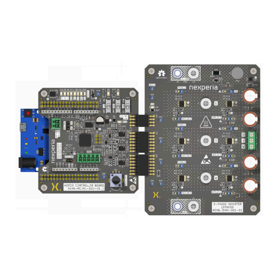
Nexperia NEVB-MCTRL-100-01-3INV-001-01 User Manual (64 pages)
Motor driver evaluation kit
Brand:
Nexperia
| Category:
Motherboard
| Size: 35 MB
Table of Contents
Table of Contents
2
Introduction
3
Fig. 1. Leonardo R3 Development Board, Motor Controller Board and 3-Phase Inverter Board
3
Motor Evaluation Kit Specifications
4
Fig. 2. BLDC Motor Control Kit Block Diagram
4
Safety Precautions
5
Getting Started
6
Fig. 3. BLDC Motor Driver Kit Overview
6
Phase Inverter Board
7
Power Supply and High-Side Current Monitoring
7
Fig. 4. 3-Phase Inverter Board Connector Locations
7
Half-Bridge Mosfets
8
Table 1. 3-Phase Inverter Board; Supply Locations
8
Fig. 6. Half-Bridge MOSFET Pairs
9
Table 2. Half-Bridge MOSFET Designations
9
Interface Connector
10
Table 3. J10 / J11 / J12 VIN Interface Connectors
10
Fig. 7. Motor Phase Terminal Block
10
Fig. 8. Interface Connector
10
Probing Signals
12
Fig. 9. 3-Phase Inverter Board with Loop Terminals Populated for Test Points
12
Fig. 10. 3-Phase Inverter Board with no Components Populated for Test Points
12
Fig. 11. 3-Phase Inverter Board with 2.54 MM and 5.08 MM Pin Headers Populated for Test Points
13
Motor Controller Board
14
DC-To-DC Converter to Generate VDD
14
Fig. 12. Motor Controller Board Connector Locations
14
Fig. 14. Gate Driver Circuit
15
Gate Driver for Mosfets
15
Fig. 13. DC-To-DC Step-Down Regulator
15
Position Sensor Inputs
16
Table 4. Hall-Effect Input Connector; J12
16
Fig. 15. Hall-Effect Sensor Input Connections
16
Development Board (Microcontroller) Connections
17
Fig. 16. Connections to Development Board (E.g. Leonardo R3 Development Board)
17
Table 5. Development Board Power Connector; J4
18
Table 6. Development Board ADC Signal Connector; J5
18
Table 7. Development Board Fault Status and MOSFET Gate Driver Signal Connector; J7 (IOH)
19
Table 8. Development Board Motor Direction and MOSFET Gate Driver Signal Connector; J8 (IOL)
19
Table 9. Connection for Alternative MCU Development Boards (E.g. Nucleo); J3
20
Table 10. Connection for Alternative MCU Development Boards (E.g. Nucleo); J9
21
Interface Signals to the 3-Phase Inverter Board
21
Table 11. Interface Connectors; J10 and J11
22
Fig. 17. Interface Signals to the 3-Phase Inverter Board
22
Back-EMF Zero-Crossing Detection Circuit
23
Motor Control Board User Inputs
23
Fig. 18. Phase Voltage Sense Circuit
23
MUX, Fault and Over-Voltage Leds
24
Fig. 19. Motor Control Board User Inputs
24
Fig. 20. MUX, Fault Leds, and Over-Voltage Leds
24
Default Settings
25
Default Jumper Settings
25
Table 12. Fault Status Leds
25
Fig. 21. Motor Control Board; Default Jumper Positions
26
Default Motor Controls
26
Connecting the BLDC Kit
27
Fig. 22. Default Motor Controls and Speed Control Position
27
Connecting the 3-Phase BLDC Motor
28
Table 13. Motor Controller to 3-Phase Inverter Board
28
Fig. 23. Connecting the BLDC Kit Boards
28
Default Motor Controller Board Voltages
29
Table 14. Default Motor Controller Board Voltages
29
Fig. 24. Hall Sensor and Motor Phase Wire Connections
29
BLDC Kit Software
30
Arduino ™ Software Installation
30
Code Documentation
31
Importing the Project and Uploading the Code
31
Connecting and Selecting the Development Board
31
Setting up the Project
31
Default Firmware Configuration
32
Remote Operation
32
SCPI Implementation
32
Firmware SCPI Command Set
32
Using Remote Mode
33
Table 15. Firmware SCPI Command Set
33
Customized Operation
35
Using a Different Motor
35
Table 16. Motor Connections
35
Using a Different Motor Algorithm
36
Using Different Mosfets
36
Design Details
36
Motor Controller Board Schematics
37
Fig. 25. Motor Controller Board Schematic Sheet 1
37
Fig. 26. Motor Controller Board Schematic Sheet 2
38
Fig. 27. Motor Controller Board Schematic Sheet 3
39
Fig. 28. Motor Controller Board Schematic Sheet 4
40
Fig. 29. Motor Controller Board Schematic Sheet 5
41
3-Phase Inverter Board Schematics
42
Fig. 30. 3-Phase Inverter Board Schematic Sheet 1
42
Fig. 31. 3-Phase Inverter Board Schematic Sheet 2
43
Fig. 32. 3-Phase Inverter Board Schematic Sheet 3
44
Motor Controller Board PCB Layout
45
Fig. 33. Motor Controller Board PCB - Top Layer
45
Fig. 34. Motor Controller Board PCB - Inner Layer 1
46
Fig. 35. Motor Controller Board PCB - Inner Layer 2
47
Fig. 36. Motor Controller Board PCB - Bottom Layer
48
3-Phase Inverter Board PCB Layout
49
Fig. 37. 3-Phase Inverter Board PCB - Top Layer
49
Fig. 38. 3-Phase Inverter Board PCB - Inner Layer 1
50
Fig. 39. 3-Phase Inverter Board PCB - Inner Layer 2
51
Fig. 40. 3-Phase Inverter Board PCB - Bottom Layer
52
Bill of Materials
53
Table 17. Motor Control Board (NEVB-MCTRL-100-01)
53
Table 18. 3-Phase Inverter Board (NEVB-3INV-001-01) Bill of Materials
57
Revision History
60
Terms and Conditions
60
Table 19. Revision History
60
Legal Information
62
Um90029 Nexperia List of Tables
63
Advertisement
Advertisement
Related Products
Nexperia NEVB-MTR1-KIT1
Nexperia NCA9555BY
Nexperia NCA9535PW
Nexperia NCA9539PW
Nexperia NBM5100
Nexperia NBM7100
Nexperia NBM5100A
Nexperia NBM7100B
Nexperia NX-HB-GAN3R2-BSC
Nexperia NMUX1237GW
Nexperia Categories
Motherboard
Multiplexer
More Nexperia Manuals
Login
Sign In
OR
Sign in with Facebook
Sign in with Google
Upload manual
Upload from disk
Upload from URL