Bose ControlSpace EX-1280C Service Manual
Conferencing processor
Hide thumbs
Also See for ControlSpace EX-1280C:
- Installation and operation manual (36 pages) ,
- Installation & operation manual (36 pages)

Subscribe to Our Youtube Channel
Related Manuals for Bose ControlSpace EX-1280C


Summary of Contents for Bose ControlSpace EX-1280C
- Page 1 Bose ControlSpace EX-1280C ® ® Conferencing Processor Service Manual ©2017 Bose Corporation Reference Number 772234-SM Revision 00...
-
Page 2: Table Of Contents
CONTENTS Safety Information.............................3 Warranty..............................3 Product Versions and Accessories......................3 Product Description..........................4-5 Specifications............................6-7 Electrostatic Discharge Sensitive (ESDS) Device Handling..............7 Part List Notes............................7 Packaging Part List............................8 Figure 1. Packaging Exploded View......................8 Main Part List.............................9 Exploded View............................10 Figure 2. ControlSpace EX 1280C Exploded View................10 ®... -
Page 3: Safety Information
THIS DOCUMENT CONTAINS PROPRIETARY INFORMATION OF BOSE CORPORATION WHICH IS BEING FURNISHED ONLY FOR THE PURPOSE OF SERVICING THE IDENTIFIED BOSE PRODUCT BY AN AUTHORIZED BOSE SERVICE CENTER, AND SHALL NOT BE REPRODUCED OR USED FOR ANY OTHER PURPOSE. WARRANTY... -
Page 4: Product Description
Bose ControlSpace Designer software, available as a free download from pro.Bose.com, enables PC setup, control, and monitoring of the Bose ControlSpace EX-1280C conferencing processor. A separate document, the ControlSpace Designer Software Guide, can be downloaded as a PDF from pro.Bose. - Page 5 14 - Telephone Line: Connect to analog telephone connections worldwide, using an RJ-11 connection. 15 - CC-16 Port: Connect to a Bose CC-16 zone controller or other control interfaces that use a RS-485 connection, such as the Bose ControlCenter CC-1, CC-2, or CC-3 zone controller.
-
Page 6: Specifications
SPECIFICATIONS INTEGRATED DSP Signal Processor/CPU 32-bit fixed/floating-point DSP 456 MHz/ARM Cortex-A8 600MHz Maximum Calculation 3.6 GIPS / 2.7 GFLOPS Delay 43 s Audio Latency 860 s (analog in to analog out) A/D and D/A Converters 24-bit Sample Rate 48 kHz ANALOG AUDIO INPUTS Input Channels 12 balanced, mic/line level... -
Page 7: Electrostatic Discharge Sensitive (Esds) Device Handling
Network Control Ethernet (RJ-45), 1Gb RS-232/485 ports RS-232 (DTE) & Bose CC-16 (RS-485 master); 3.81 mm Phoenix Contact®, 3-pin Audio Channel Capacity 166 channels (20 analog, 8 AmpLink out, 64x64 Dante, 4 VoIP, 4 USB, 2 PSTN) Electrostatic Discharge Sensitive (ESDS) Device Handling This unit contains ESDS devices. -
Page 8: Packaging Part List
PACKAGING PART LIST ControlSpace EX 1280C (see Figure 1) ® Item Num- Description Part Number Qty. Note CARTON, DSP, SVC 785543-001S CONNECTOR KIT, DSP 787147-001S PEARL FORM, ENDCAP, SVC 785550-001S POLY BAG, L420XW550MM 785546-0010 POLY BAG, L320xW217x0.5mm (INSTALL GUIDE) GUIDE, INSTALL, DSP 788755-0010 WAFER SEAL, 80MM AC LINE CORD, IEC, C13, US/CAN... -
Page 9: Main Part List
MAIN PART LIST ControlSpace EX 1280C (see Figure 2) ® Item Description Part Number Qty. Note Number HARNESS, PS-MAIN, 22AWG, 10 COND 370437-0010 CABLE, GROUND INLET, GRN/YEL (AC GROUND) 530498-001S COVER, DSP, BLK, SVC (TOP COVER) 777061-011S SCREW, MSB, M3x6MM, BLACK SCREW, SI, MSF, M3x5.5MM 370493-0110 SCREW, MSB, M3x6MM, W/WASHER... -
Page 10: Exploded View
EXPLODED VIEW 13 14 11 12 Figure 2. ControlSpace EX 1280C Exploded View ®... -
Page 11: Main Dsp Pcb Part List
MAIN DSP PCB PART LIST Resistors Reference Description Vendor Vendor Part Number Note Designator 0.0, 1/10W, JUMPER, 0402, SM PANASONIC ERJ-2GE0R00X 10.0K, 1/10W, 1%, 0402, SM PANASONIC ERJ-2RKF1002X 10.0K, 1/10W, 1%, 0402, SM PANASONIC ERJ-2RKF1002X 0.0, 1/10W, JUMPER, 0402, SM PANASONIC ERJ-2GE0R00X 0.0, 1/10W, JUMPER, 0402, SM... - Page 12 MAIN DSP PCB PART LIST Resistors (continued) Reference Description Vendor Vendor Part Number Note Designator 0.0, 1/10W, JUMPER, 0402, SM PANASONIC ERJ-2GE0R00X 33.0, 1/10W, 1%, 0402, SM PANASONIC ERJ-2RKF33R0X 33.0, 1/10W, 1%, 0402, SM PANASONIC ERJ-2RKF33R0X 33.0, 1/10W, 1%, 0402, SM PANASONIC ERJ-2RKF33R0X 10.0, 1/10W, 1%, 0402, SM...
- Page 13 MAIN DSP PCB PART LIST Resistors (continued) Reference Description Vendor Vendor Part Number Note Designator R110 10.0K, 1/10W, 1%, 0402, SM PANASONIC ERJ-2RKF1002X R112 33.0, 1/10W, 1%, 0402, SM PANASONIC ERJ-2RKF33R0X R113 10.0, 1/10W, 1%, 0402, SM PANASONIC ERJ-2RKF10R0X R114 33.0, 1/10W, 1%, 0402, SM PANASONIC ERJ-2RKF33R0X...
- Page 14 MAIN DSP PCB PART LIST Resistors (continued) Reference Description Vendor Vendor Part Number Note Designator R160 33.0, 1/10W, 1%, 0402, SM PANASONIC ERJ-2RKF33R0X R161 4.99K, 1/10W, 1%, 0402, SM PANASONIC ERJ-2RKF4991X R162 33.0, 1/10W, 1%, 0402, SM PANASONIC ERJ-2RKF33R0X R163 33.0, 1/10W, 1%, 0402, SM PANASONIC ERJ-2RKF33R0X...
- Page 15 MAIN DSP PCB PART LIST Resistors (continued) Reference Description Vendor Vendor Part Number Note Designator R208 33.0, 1/10W, 1%, 0402, SM PANASONIC ERJ-2RKF33R0X R209 33.0, 1/10W, 1%, 0402, SM PANASONIC ERJ-2RKF33R0X R210 33.0, 1/10W, 1%, 0402, SM PANASONIC ERJ-2RKF33R0X R211 33.0, 1/10W, 1%, 0402, SM PANASONIC ERJ-2RKF33R0X...
- Page 16 MAIN DSP PCB PART LIST Resistors (continued) Reference Description Vendor Vendor Part Number Note Designator R261 4.99K, 1/10W, 1%, 0402, SM PANASONIC ERJ-2RKF4991X R262 1.00K, 1/10W, 1%, 0402, SM PANASONIC ERJ-2RKF1001X R263 200, 1/10W, 1%, 0402, SM PANASONIC ERJ-2RKF2000X R264 200, 1/10W, 1%, 0402, SM PANASONIC ERJ-2RKF2000X...
- Page 17 MAIN DSP PCB PART LIST Resistors (continued) Reference Description Vendor Vendor Part Number Note Designator R329 2.00K, 1/10W, 1%, 0402, SM PANASONIC ERJ-2RKF2001X R330 2.00K, 1/10W, 1%, 0402, SM PANASONIC ERJ-2RKF2001X R331 2.00K, 1/10W, 1%, 0402, SM PANASONIC ERJ-2RKF2001X R332 100, 1/10W, 1%, 0402, SM PANASONIC ERJ-2RKF1000X...
- Page 18 MAIN DSP PCB PART LIST Resistors (continued) Reference Description Vendor Vendor Part Number Note Designator R373 10.0K, 1/10W, 1%, 0402, SM PANASONIC ERJ-2RKF1002X R374 10.0K, 1/10W, 1%, 0402, SM PANASONIC ERJ-2RKF1002X R375 10.0K, 1/10W, 1%, 0402, SM PANASONIC ERJ-2RKF1002X R376 10.0K, 1/10W, 1%, 0402, SM PANASONIC ERJ-2RKF1002X...
- Page 19 MAIN DSP PCB PART LIST Resistors (continued) Reference Description Vendor Vendor Part Number Note Designator R418 10.0K, 1/10W, 1%, 0402, SM PANASONIC ERJ-2RKF1002X R419 10.0K, 1/10W, 1%, 0402, SM PANASONIC ERJ-2RKF1002X R420 10.0K, 1/10W, 1%, 0402, SM PANASONIC ERJ-2RKF1002X R446 100, 1/10W, 1%, 0402, SM PANASONIC ERJ-2RKF1000X...
- Page 20 MAIN DSP PCB PART LIST Resistors (continued) Reference Description Vendor Vendor Part Number Note Designator R490 150K, 1/10W, 1%, 0402, SM PANASONIC ERJ-2RKF1503X R491 20.0K, 1/10W, 1%, 0402, SM PANASONIC ERJ-2RKF2002X R492 56.2K, 1/10W, 1%, 0402, SM PANASONIC ERJ-2RKF5622X R493 20.0K, 1/10W, 1%, 0402, SM PANASONIC ERJ-2RKF2002X...
- Page 21 MAIN DSP PCB PART LIST Resistor Networks (continued) Reference Description Vendor Vendor Part Number Note Designator RES NET, ISO, 22, 5%, 62.5MW, 1606 ROHM MNR18ERAPJ220 RES NET, ISO, 33, 5%, 62.5MW, 1606 ROHM MNR18ERAPJ330 RES NET, ISO, 33, 5%, 62.5MW, 1606 ROHM MNR18ERAPJ330 RES NET, ISO, 22, 5%, 62.5MW, 1606...
- Page 22 MAIN DSP PCB PART LIST Capacitors (continued) Reference Description Vendor Vendor Part Number Note Designator CER, 0.1UF, 50V, 10%, X7R, 0402, SM C1005X7R1H104K050BB CER, 4.7UF, 6.3V, 10%, X5R, 0603, SM MURATA GRM188R60J475KE19D CER, 0.1UF, 50V, 10%, X7R, 0402, SM C1005X7R1H104K050BB X7R 10NF 25V +/-10% 0402 ROHS MURATA GRM155R71E103KA01D...
- Page 23 MAIN DSP PCB PART LIST Capacitors (continued) Reference Description Vendor Vendor Part Number Note Designator CER, 10UF, 25V, 10%, X5R, 0805, SM MURATA GRM21BR61E106KA73L X7R 10NF 25V +/-10% 0402 ROHS MURATA GRM155R71E103KA01D X7R 10NF 25V +/-10% 0402 ROHS MURATA GRM155R71E103KA01D CER, 10UF, 25V, 10%, X5R, 0805, SM MURATA GRM21BR61E106KA73L...
- Page 24 MAIN DSP PCB PART LIST Capacitors (continued) Reference Description Vendor Vendor Part Number Note Designator C120 X7R 10NF 25V +/-10% 0402 ROHS MURATA GRM155R71E103KA01D C121 X7R 10NF 25V +/-10% 0402 ROHS MURATA GRM155R71E103KA01D C122 CER, 1UF, 25V, 10%, X7R, 0603 TAIYO YUDEN TMK107B7105KA-T C123...
- Page 25 MAIN DSP PCB PART LIST Capacitors (continued) Reference Description Vendor Vendor Part Number Note Designator C163 CER, 0.1UF, 50V, 10%, X7R, 0402, SM C1005X7R1H104K050BB C164 CER, 0.1UF, 50V, 10%, X7R, 0402, SM C1005X7R1H104K050BB C165 CER, 0.1UF, 50V, 10%, X7R, 0402, SM C1005X7R1H104K050BB C166 CER, 0.1UF, 50V, 10%, X7R, 0402, SM...
- Page 26 MAIN DSP PCB PART LIST Capacitors (continued) Reference Description Vendor Vendor Part Number Note Designator C208 CER, 0.1UF, 50V, 10%, X7R, 0402, SM C1005X7R1H104K050BB C209 CER, 0.1UF, 50V, 10%, X7R, 0402, SM C1005X7R1H104K050BB C210 CER, 0.1UF, 50V, 10%, X7R, 0402, SM C1005X7R1H104K050BB C211 CER, 0.1UF, 50V, 10%, X7R, 0402, SM...
- Page 27 MAIN DSP PCB PART LIST Capacitors (continued) Reference Description Vendor Vendor Part Number Note Designator C251 CER, 0.1UF, 50V, 10%, X7R, 0402, SM C1005X7R1H104K050BB C252 CER, 10UF, 25V, 10%, X5R, 0805, SM MURATA GRM21BR61E106KA73L C253 CER, 0.1UF, 50V, 10%, X7R, 0402, SM C1005X7R1H104K050BB C254 CER, 0.1UF, 50V, 10%, X7R, 0402, SM...
- Page 28 MAIN DSP PCB PART LIST Capacitors (continued) Reference Description Vendor Vendor Part Number Note Designator C301 X7R 10NF 25V +/-10% 0402 ROHS MURATA GRM155R71E103KA01D C302 CER, 10UF, 25V, 10%, X5R, 0805, SM MURATA GRM21BR61E106KA73L C303 CER, 0.1UF, 50V, 10%, X7R, 0402, SM C1005X7R1H104K050BB C304 CER, 10UF, 25V, 10%, X5R, 0805, SM...
- Page 29 MAIN DSP PCB PART LIST Capacitors (continued) Reference Description Vendor Vendor Part Number Note Designator C348 CER, 0.1UF, 50V, 10%, X7R, 0402, SM C1005X7R1H104K050BB C349 CER, 2.2UF, 16V, 20%, X5R, 0805, SM MURATA GRM21BR61C225KA88L C350 CER, 0.1UF, 50V, 10%, X7R, 0402, SM C1005X7R1H104K050BB C351 CER, 0.1UF, 50V, 10%, X7R, 0402, SM...
- Page 30 MAIN DSP PCB PART LIST Capacitors (continued) Reference Description Vendor Vendor Part Number Note Designator C391 CER, 0.1UF, 50V, 10%, X7R, 0402, SM C1005X7R1H104K050BB C392 CER, 10UF, 25V, 10%, X5R, 0805, SM MURATA GRM21BR61E106KA73L C393 CER, 10UF, 25V, 10%, X5R, 0805, SM MURATA GRM21BR61E106KA73L C394...
- Page 31 MAIN DSP PCB PART LIST Capacitors (continued) Reference Description Vendor Vendor Part Number Note Designator C435 CER, 10UF, 25V, 10%, X5R, 0805, SM MURATA GRM21BR61E106KA73L C436 CER, 10UF, 25V, 10%, X5R, 0805, SM MURATA GRM21BR61E106KA73L C437 CER, 0.1UF, 50V, 10%, X7R, 0402, SM C1005X7R1H104K050BB C438 CER, 0.1UF, 50V, 10%, X7R, 0402, SM...
- Page 32 MAIN DSP PCB PART LIST Capacitors (continued) Reference Description Vendor Vendor Part Number Note Designator C480 CER, 8200PF, 50V, 10%, X7R, 0402, SM MURATA GRM155R71H822KA88D C481 PANASONIC EEE-FTH101XAP EL, ALUM, 100UF, 50V, 20%, SMT_D, SM C482 CER, 0.1UF, 50V, 10%, X7R, 0402, SM C1005X7R1H104K050BB C483 CER, 0.1UF, 50V, 10%, X7R, 0402, SM...
- Page 33 MAIN DSP PCB PART LIST Ferrite Beads (continued) Reference Description Vendor Vendor Part Number Note Designator FERR BEAD, 0.8A, 150 OHM, 0805 LAIRD-SIGNAL LI0805H151R-10 FERR BEAD, 0.8A, 150 OHM, 0805 LAIRD-SIGNAL LI0805H151R-10 FERR BEAD, 0.8A, 150 OHM, 0805 LAIRD-SIGNAL LI0805H151R-10 FERR BEAD, 0.8A, 150 OHM, 0805 LAIRD-SIGNAL LI0805H151R-10...
- Page 34 MAIN DSP PCB PART LIST Diodes (continued) Reference Description Vendor Vendor Part Number Note Designator 4CH ESD SOL W/CLAMP 6SON TEXAS INST. TPD4S012DRYR 4CH ESD SOL W/CLAMP 6SON TEXAS INST. TPD4S012DRYR TVS SC70-3 TEXAS INST. TPD2E007DCKR TVS 5VWM SMD BOURNS SMAJ5.0A TVS 5VWM SMD BOURNS...
- Page 35 MAIN DSP PCB PART LIST Transistors (continued) Reference Description Vendor Vendor Part Number Note Designator MOSFET N-CH 60V 115MA SOT-23 FAIRCHILD 2N7002 MOSFET N-CH 60V 115MA SOT-23 FAIRCHILD 2N7002 MOSFET N-CH 60V 115MA SOT-23 FAIRCHILD 2N7002 MOSFET N-CH 60V 115MA SOT-23 FAIRCHILD 2N7002 MOSFET N-CH 60V 115MA SOT-23...
- Page 36 MAIN DSP PCB PART LIST Integrated Circuits (continued) Reference Description Vendor Vendor Part Number Note Designator I/O EXPANDER I2C 40B 56TSSOP NXP SEMI PCA9505DGG,118 REG LDO 1V 0.4A SOT23-5 ON SEMI NCP4671DSN10T1G D-TYPE POS TRG SNGL SC70-5 TEXAS INST. SN74AUP1G80DCKR LINE DRVR/RCVR M-LVDS 8-SOIC TEXAS INST.
- Page 37 MAIN DSP PCB PART LIST Miscellaneous (continued) Reference Description Vendor Vendor Part Number Note Designator CON, TERM BLOCK, 8A, 6, ORANGE, PHOENIX 1701044 3.81MM, RA, TH CONN, FLT, 0.5mm, TOP ENTRY, SMT 40FLT-SM2-TB CONN, FLT, 0.5mm, TOP ENTRY, SMT 40FLT-SM2-TB CONN FFC VERT 24POS 0.50MM SMD SFV24R-2STE1HLF CONN FFC VERT 24POS 0.50MM SMD...
-
Page 38: Input Pcb Part List
INPUT PCB PART LIST Resistors Reference Description Vendor Vendor Part Number Note Designator R1000 330K, 1/10W, 0603, 1% Panasonic ERJ-3EKF3303V R1001 100 OHM, 1/8W, 0805, 1% Yageo RC0805FR-07100RL R1002 20K, 1/10W, 0603, 1%, T&R RK73H1JTTD2002F R1003 6.8K, 1/2W, 1210, 1% Panasonic ERJ-14NF6801U R1004... - Page 39 INPUT PCB PART LIST Resistors (continued) Reference Description Vendor Vendor Part Number Note Designator R1071 IND82.5 OHM, 1/10W, 0603, 1% RK73H1JTTD82R5F R1072 19.1 OHM, 1/10W, 0603, 1% RK73H1JTTD19R1F R1073 0 OHM, 1A, 0603 RK73Z1JTTD R1100 330K, 1/10W, 0603, 1% Panasonic ERJ-3EKF3303V R1101 100 OHM, 1/8W, 0805, 1%...
- Page 40 INPUT PCB PART LIST Resistors (continued) Reference Description Vendor Vendor Part Number Note Designator R1168 820 OHM, 1/10W, 0603, 1% RK73H1JTTD8200F R1169 IND82.5 OHM, 1/10W, 0603, 1% RK73H1JTTD82R5F R1170 19.1 OHM, 1/10W, 0603, 1% RK73H1JTTD19R1F R1171 IND82.5 OHM, 1/10W, 0603, 1% RK73H1JTTD82R5F R1172 19.1 OHM, 1/10W, 0603, 1%...
- Page 41 INPUT PCB PART LIST Resistors (continued) Reference Description Vendor Vendor Part Number Note Designator R1265 220 OHM, 1/10W, 0603, 1% RK73H1JTTD2200F R1266 820 OHM, 1/10W, 0603, 1% RK73H1JTTD8200F R1267 220 OHM, 1/10W, 0603, 1% RK73H1JTTD2200F R1268 820 OHM, 1/10W, 0603, 1% RK73H1JTTD8200F R1269 IND82.5 OHM, 1/10W, 0603, 1%...
- Page 42 INPUT PCB PART LIST Resistors (continued) Reference Description Vendor Vendor Part Number Note Designator R1361 10K, 1/10W, 0603, 1% RK73H1JTTD1002F R1363 3.3K, 1/10W, 0603, 1% RK73H1JTTD3301F R1364 3.3K, 1/10W, 0603, 1% RK73H1JTTD3301F R1365 220 OHM, 1/10W, 0603, 1% RK73H1JTTD2200F R1366 820 OHM, 1/10W, 0603, 1% RK73H1JTTD8200F R1367...
- Page 43 INPUT PCB PART LIST Resistors (continued) Reference Description Vendor Vendor Part Number Note Designator R1458 10K, 1/10W, 0603, 1% RK73H1JTTD1002F R1459 39K, 1/10W, 0603, 1% RK73H1JTTD3902F R1460 39K, 1/10W, 0603, 1% RK73H1JTTD3902F R1461 10K, 1/10W, 0603, 1% RK73H1JTTD1002F R1463 3.3K, 1/10W, 0603, 1% RK73H1JTTD3301F R1464 3.3K, 1/10W, 0603, 1%...
- Page 44 INPUT PCB PART LIST Resistors (continued) Reference Description Vendor Vendor Part Number Note Designator R1555 200K, 1/10W, 0603, 1% RK73H1JTTD2003F R1556 0 OHM, 1A, 0603 RK73Z1JTTD R1557 0 OHM, 1A, 0603 RK73Z1JTTD R1558 10K, 1/10W, 0603, 1% RK73H1JTTD1002F R1559 39K, 1/10W, 0603, 1% RK73H1JTTD3902F R1560 39K, 1/10W, 0603, 1%...
- Page 45 INPUT PCB PART LIST Resistors (continued) Reference Description Vendor Vendor Part Number Note Designator R1656 4.99K, 1/10W, 0603, 1%, T&R RK73H1JTTD4991F R1657 4.99K, 1/10W, 0603, 1%, T&R RK73H1JTTD4991F R1658 330 OHM, 1/10W, 0603, 1% RK73H1JTTD3300F R1659 4.99K, 1/10W, 0603, 1%, T&R RK73H1JTTD4991F R1660 330 OHM, 1/10W, 0603, 1%...
- Page 46 INPUT PCB PART LIST Resistors (continued) Reference Description Vendor Vendor Part Number Note Designator R1761 330 OHM, 1/10W, 0603, 1% RK73H1JTTD3300F R1762 330 OHM, 1/10W, 0603, 1% RK73H1JTTD3300F R1763 91 OHM, 1/10W, 0603, 1% RK73H1JTTD91R0F R1764 91 OHM, 1/10W, 0603, 1% RK73H1JTTD91R0F R1765 91 OHM, 1/10W, 0603, 1%...
- Page 47 INPUT PCB PART LIST Resistors (continued) Reference Description Vendor Vendor Part Number Note Designator R1866 91 OHM, 1/10W, 0603, 1% RK73H1JTTD91R0F R1867 2.7K, 1/10W, 0603, 1% RK73H1JTTD2701F R1868 2.7K, 1/10W, 0603, 1% RK73H1JTTD2701F R1900 20 OHM, 1/10W 0603 1% T&R RK73H1JTTD20R0F R1902 10K, 1/10W, 0603, 1%...
- Page 48 INPUT PCB PART LIST Resistors (continued) Reference Description Vendor Vendor Part Number Note Designator R2103 0 OHM, 1A, 0603 RK73Z1JTTD R2104 20K, 1/10W, 0603, 1%, T&R RK73H1JTTD2002F R2105 0 OHM, 1A, 0603 RK73Z1JTTD R2106 0 OHM, 1A, 0603 RK73Z1JTTD R2150 10K, 1/10W, 0603, 1% RK73H1JTTD1002F R2151...
- Page 49 INPUT PCB PART LIST Capacitors (continued) Reference Description Vendor Vendor Part Number Note Designator C1006 100PF, 50V, 5%, 0603 Murata GRM1882C1H101JA01D C1007 SMD, E 33UF, 25V, 20%, 55C Panasonic EEE-FT1E330AR C1008 SMD, E 33UF, 25V, 20%, 55C Panasonic EEE-FT1E330AR C1009 Y5V ,0.1UF, 50V, 20%, 0603 Murata GRM188F11H104ZA01D...
- Page 50 INPUT PCB PART LIST Capacitors (continued) Reference Description Vendor Vendor Part Number Note Designator C1111 100PF, 50V, 5%, 0603 Murata GRM1882C1H101JA01D C1112 47PF, 50V, 5%, 0603 Murata GRM1882C1H470JA01D C1113 47PF, 50V, 5%, 0603 Murata GRM1882C1H470JA01D C1114 Y5V ,0.1UF, 50V, 20%, 0603 Murata GRM188F11H104ZA01D C1115...
- Page 51 INPUT PCB PART LIST Capacitors (continued) Reference Description Vendor Vendor Part Number Note Designator C1216 SMD, E 100UF, 6.3V, 20%, 40C United EMVA6R3ADA101ME55G C1217 SMD, E 100UF, 6.3V, 20%, 40C United EMVA6R3ADA101ME55G C1218 Y5V ,0.1UF, 50V, 20%, 0603 Murata GRM188F11H104ZA01D C1250 Y5V ,0.1UF, 50V, 20%, 0603 Murata...
- Page 52 INPUT PCB PART LIST Capacitors (continued) Reference Description Vendor Vendor Part Number Note Designator C1352 Y5V ,0.1UF, 50V, 20%, 0603 Murata GRM188F11H104ZA01D C1353 SMD, E 4.7UF, 63V, 20%, 40C United EMVA630ADA4R7ME55G C1354 SMD, E 4.7UF, 63V, 20%, 40C United EMVA630ADA4R7ME55G C1355 100PF, 50V, 5%, 0603 Murata...
- Page 53 INPUT PCB PART LIST Capacitors (continued) Reference Description Vendor Vendor Part Number Note Designator C1457 SMD, E 33UF, 25V, 20%, 55C Panasonic EEE-FT1E330AR C1458 SMD, E 33UF, 25V, 20%, 55C Panasonic EEE-FT1E330AR C1459 Y5V ,0.1UF, 50V, 20%, 0603 Murata GRM188F11H104ZA01D C1460 Y5V ,0.1UF, 50V, 20%, 0603 Murata...
- Page 54 INPUT PCB PART LIST Capacitors (continued) Reference Description Vendor Vendor Part Number Note Designator C1562 47PF, 50V, 5%, 0603 Murata GRM1882C1H470JA01D C1563 47PF, 50V, 5%, 0603 Murata GRM1882C1H470JA01D C1564 Y5V ,0.1UF, 50V, 20%, 0603 Murata GRM188F11H104ZA01D C1565 Y5V ,0.1UF, 50V, 20%, 0603 Murata GRM188F11H104ZA01D C1566...
- Page 55 INPUT PCB PART LIST Capacitors (continued) Reference Description Vendor Vendor Part Number Note Designator C1708 Y5V ,0.1UF, 50V, 20%, 0603 Murata GRM188F11H104ZA01D C1709 Y5V ,0.1UF, 50V, 20%, 0603 Murata GRM188F11H104ZA01D C1710 Y5V ,0.1UF, 50V, 20%, 0603 Murata GRM188F11H104ZA01D C1711 Y5V ,0.1UF, 50V, 20%, 0603 Murata GRM188F11H104ZA01D C1712...
- Page 56 INPUT PCB PART LIST Capacitors (continued) Reference Description Vendor Vendor Part Number Note Designator C1859 Y5V ,0.1UF, 50V, 20%, 0603 Murata GRM188F11H104ZA01D C1860 Y5V ,0.1UF, 50V, 20%, 0603 Murata GRM188F11H104ZA01D C1861 Y5V ,0.1UF, 50V, 20%, 0603 Murata GRM188F11H104ZA01D C1862 47PF, 50V, 5%, 0603 Murata GRM1882C1H470JA01D C1863...
- Page 57 INPUT PCB PART LIST Capacitors (continued) Reference Description Vendor Vendor Part Number Note Designator C1968 Y5V ,0.1UF, 50V, 20%, 0603 Murata GRM188F11H104ZA01D C1969 SMD, E 10UF, 16V, 20%, 55C NIPPON EMVY160ADA100MD55G C2000 SMD, E 33UF, 25V, 20%, 55C Panasonic EEE-FT1E330AR C2001 SMD, E 2.2UF, 50V, 20%, 55C United...
- Page 58 INPUT PCB PART LIST Ferrite Beads Reference Description Vendor Vendor Part Number Note Designator FB1000 0 OHM, 1A, 0603 RK73Z1JTTD FB1001 CHIP, IND, 1K, 25%, 0603 Taiyo Yud BK1608HS102-T FB1002 CHIP, IND, 1K, 25%, 0603 Taiyo Yud BK1608HS102-T FB1050 0 OHM, 1A, 0603 RK73Z1JTTD FB1051 CHIP, IND, 1K, 25%, 0603...
- Page 59 INPUT PCB PART LIST Diodes Reference Description Vendor Vendor Part Number Note Designator D1000 BAV99LT1G, SOT-23 ON Semi BAV99LT1G D1001 BAV99LT1G, SOT-23 ON Semi BAV99LT1G D1050 BAV99LT1G, SOT-23 ON Semi BAV99LT1G D1051 BAV99LT1G, SOT-23 ON Semi BAV99LT1G D1100 BAV99LT1G, SOT-23 ON Semi BAV99LT1G D1101...
- Page 60 INPUT PCB PART LIST Integrated Circuits Reference Description Vendor Vendor Part Number Note Designator U1000 SWITCH, QUAD, ADG451BRUZ, TSSOP Analog ADG451BRUZ Devices U1001 NJM4580E-TE1-#ZZZB, EMP8 NJRC NJM4580E-TE1 U1050 SWITCH, QUAD, ADG451BRUZ, TSSOP Analog ADG451BRUZ Devices U1051 NJM4580E-TE1-#ZZZB, EMP8 NJRC NJM4580E-TE1 U1100 SWITCH, QUAD, ADG451BRUZ, TSSOP Analog...
- Page 61 INPUT PCB PART LIST Integrated Circuits (continued) U1850 NJM4580E-TE1-#ZZZB, EMP8 NJRC NJM4580E-TE1 U1851 NJM4580E-TE1-#ZZZB, EMP8 NJRC NJM4580E-TE1 U1900 ADC, AK5388AEQ AKM Semi AK5388AEQ U1950 ADC, AK5388AEQ AKM Semi AK5388AEQ U2000 ADC, AK5388AEQ AKM Semi AK5388AEQ U2050 I2C, BUS, PCA9505DGG, 118 TSSOP NXP Semi PCA9505DGG,118 U2051...
-
Page 62: Output Pcb Part List
OUTPUT PCB PART LIST Resistors Reference Description Vendor Vendor Part Number Note Designator R100 0 OHM, 1A, 0603 RK73Z1JTTD R101 0 OHM, 1A, 0603 RK73Z1JTTD R102 10K, 1/10W, 0603, 1% RK73H1JTTD1002F R103 10K, 1/10W, 0603, 1% RK73H1JTTD1002F R104 10K, 1/10W, 0603, 1% RK73H1JTTD1002F R105 10K, 1/10W, 0603, 1%... - Page 63 OUTPUT PCB PART LIST Resistors (continued) Reference Description Vendor Vendor Part Number Note Designator R200 0 OHM, 1A, 0603 RK73Z1JTTD R201 0 OHM, 1A, 0603 RK73Z1JTTD R202 10K, 1/10W, 0603, 1% RK73H1JTTD1002F R203 10K, 1/10W, 0603, 1% RK73H1JTTD1002F R204 10K, 1/10W, 0603, 1% RK73H1JTTD1002F R205 10K, 1/10W, 0603, 1%...
- Page 64 OUTPUT PCB PART LIST Resistors (continued) Reference Description Vendor Vendor Part Number Note Designator R273 120K, 1/10W, 0603, 1%, T&R RK73H1JTTD1203F R300 0 OHM, 1A, 0603 RK73Z1JTTD R301 0 OHM, 1A, 0603 RK73Z1JTTD R302 10K, 1/10W, 0603, 1% RK73H1JTTD1002F R303 10K, 1/10W, 0603, 1% RK73H1JTTD1002F R304...
- Page 65 OUTPUT PCB PART LIST Resistors (continued) Reference Description Vendor Vendor Part Number Note Designator R372 120K, 1/10W, 0603, 1%, T&R RK73H1JTTD1203F R373 120K, 1/10W, 0603, 1%, T&R RK73H1JTTD1203F R400 0 OHM, 1A, 0603 RK73Z1JTTD R401 0 OHM, 1A, 0603 RK73Z1JTTD R402 10K, 1/10W, 0603, 1% RK73H1JTTD1002F...
- Page 66 OUTPUT PCB PART LIST Resistors (continued) Reference Description Vendor Vendor Part Number Note Designator R471 33 OHM, 1/10W, 0603, 1% RK73H1JTTD33R0F R472 120K, 1/10W, 0603, 1%, T&R RK73H1JTTD1203F R473 120K, 1/10W, 0603, 1%, T&R RK73H1JTTD1203F R500 120K, 1/10W, 0603, 1%, T&R RK73H1JTTD1203F R501 120K, 1/10W, 0603, 1%, T&R...
- Page 67 OUTPUT PCB PART LIST Resistors (continued) Reference Description Vendor Vendor Part Number Note Designator R556 1.69K, 1/10W, 0603, 1% Panasonic ERJ-3EKF1691V R557 1.69K, 1/10W, 0603, 1% Panasonic ERJ-3EKF1691V R558 1.69K, 1/10W, 0603, 1% Panasonic ERJ-3EKF1691V R559 1.69K, 1/10W, 0603, 1% Panasonic ERJ-3EKF1691V R560...
- Page 68 OUTPUT PCB PART LIST Resistors (continued) Reference Description Vendor Vendor Part Number Note Designator R616 549 OHM, 1/10W, 0603, 1% Panasonic ERJ-3EKF5490V R617 549 OHM, 1/10W, 0603, 1% Panasonic ERJ-3EKF5490V R618 3.3K, 1/10W, 0603, 1% RK73H1JTTD3301F R619 3.3K, 1/10W, 0603, 1% RK73H1JTTD3301F R620 3.3K, 1/10W, 0603, 1%...
- Page 69 OUTPUT PCB PART LIST Resistors (continued) Reference Description Vendor Vendor Part Number Note Designator R675 866 OHM, 1/10W, 0603, 1% Panasonic ERJ-3EKF8660V R676 866 OHM, 1/10W, 0603, 1% Panasonic ERJ-3EKF8660V R677 866 OHM, 1/10W, 0603, 1% Panasonic ERJ-3EKF8660V R678 866 OHM, 1/10W, 0603, 1% Panasonic ERJ-3EKF8660V R679...
- Page 70 OUTPUT PCB PART LIST Resistors (continued) Reference Description Vendor Vendor Part Number Note Designator R816 10K, 1/10W, 0603, 1% RK73H1JTTD1002F R817 10K, 1/10W, 0603, 1% RK73H1JTTD1002F R850 47 OHM, 1/10W, 0603, 1%, T&R RK73H1JTTD47R0F R851 1M, 1/10W, 0603, 1%, T&R RK73H1JTTD1004F R852 10K, 1/10W, 0603, 1%...
- Page 71 OUTPUT PCB PART LIST Capacitors Reference Description Vendor Vendor Part Number Note Designator C102 NPO, 22PF, 50V, 5%, 0603 Murata GRM1885C1H220JA01D C103 NPO, 22PF, 50V, 5%, 0603 Murata GRM1885C1H220JA01D C104 NPO, 22PF, 50V, 5%, 0603 Murata GRM1885C1H220JA01D C105 NPO, 22PF, 50V, 5%, 0603 Murata GRM1885C1H220JA01D C106...
- Page 72 OUTPUT PCB PART LIST Capacitors (continued) Reference Description Vendor Vendor Part Number Note Designator C253 NPO, 22PF, 50V, 5%, 0603 Murata GRM1885C1H220JA01D C254 NPO, 22PF, 50V, 5%, 0603 Murata GRM1885C1H220JA01D C255 NPO, 22PF, 50V, 5%, 0603 Murata GRM1885C1H220JA01D C256 Y5V, 0.1UF, 50V, 20%, 0603, T&R Murata GRM188F11H104ZA01D C257...
- Page 73 OUTPUT PCB PART LIST Capacitors (continued) Reference Description Vendor Vendor Part Number Note Designator C404 NPO, 22PF, 50V, 5%, 0603 Murata GRM1885C1H220JA01D C405 NPO, 22PF, 50V, 5%, 0603 Murata GRM1885C1H220JA01D C406 Y5V, 0.1UF, 50V, 20%, 0603, T&R Murata GRM188F11H104ZA01D C407 Y5V, 0.1UF, 50V, 20%, 0603, T&R Murata GRM188F11H104ZA01D...
- Page 74 OUTPUT PCB PART LIST Capacitors (continued) Reference Description Vendor Vendor Part Number Note Designator C517 NPO, 3.6NF, 50V, 5%, 0603 Murata GRM1885C1H362JA01D C518 NPO, 3.6NF, 50V, 5%, 0603 Murata GRM1885C1H362JA01D C519 NPO, 3.6NF, 50V, 5%, 0603 Murata GRM1885C1H362JA01D C520 NPO, 1.8NF, 50V, 5%, 0603 Murata GRM1885C1H182JA01D C521...
- Page 75 OUTPUT PCB PART LIST Capacitors (continued) Reference Description Vendor Vendor Part Number Note Designator C604 NPO, 1.8NF, 50V, 5%, 0603 Murata GRM1885C1H182JA01D C605 NPO, 1.8NF, 50V, 5%, 0603 Murata GRM1885C1H182JA01D C606 NPO, 1.8NF, 50V, 5%, 0603 Murata GRM1885C1H182JA01D C607 NPO, 1.8NF, 50V, 5%, 0603 Murata GRM1885C1H182JA01D C608...
- Page 76 OUTPUT PCB PART LIST Capacitors (continued) Reference Description Vendor Vendor Part Number Note Designator C669 NPO, 3.6NF, 50V, 5%, 0603 Murata GRM1885C1H362JA01D C670 NPO, 1.8NF, 50V, 5%, 0603 Murata GRM1885C1H182JA01D C671 NPO, 1.8NF, 50V, 5%, 0603 Murata GRM1885C1H182JA01D C672 NPO, 1.8NF, 50V, 5%, 0603 Murata GRM1885C1H182JA01D C673...
- Page 77 OUTPUT PCB PART LIST Capacitors (continued) Reference Description Vendor Vendor Part Number Note Designator C800 Y5V, 0.1UF, 50V, 20%, 0603, T&R Murata GRM188F11H104ZA01D C801 Y5V, 0.1UF, 50V, 20%, 0603, T&R Murata GRM188F11H104ZA01D C802 Y5V, 0.1UF, 50V, 20%, 0603, T&R Murata GRM188F11H104ZA01D C803 Y5V, 0.1UF, 50V, 20%, 0603, T&R...
- Page 78 OUTPUT PCB PART LIST Inductors (continued) FB401 IND, 1K, 25%, 0603 Taiyo Yud BK1608HS102-T FB402 0 OHM, 1A, 0603 RK73Z1JTTD FB450 IND, 1K, 25%, 0603 Taiyo Yud BK1608HS102-T FB451 IND, 1K, 25%, 0603 Taiyo Yud BK1608HS102-T FB452 0 OHM, 1A, 0603 RK73Z1JTTD Diodes Reference...
- Page 79 OUTPUT PCB PART LIST Transistors (continued) Reference Description Vendor Vendor Part Number Note Designator Q154 MOSFET, N-CH, 2N7002K-T1-E3, SOT-23 Vishay 2N7002K-T1-E3 Q155 MOSFET, N-CH, 2N7002K-T1-E3, SOT-23 Vishay 2N7002K-T1-E3 Q200 MOSFET, N-CH, 2N7002K-T1-E3, SOT-23 Vishay 2N7002K-T1-E3 Q201 MOSFET, N-CH, 2N7002K-T1-E3, SOT-23 Vishay 2N7002K-T1-E3 Q202...
- Page 80 OUTPUT PCB PART LIST Transistors (continued) Reference Description Vendor Vendor Part Number Note Designator Q505 MOSFET, N-CH, 2N7002K-T1-E3, SOT-23 Vishay 2N7002K-T1-E3 Q550 MOSFET, N-CH, 2N7002K-T1-E3, SOT-23 Vishay 2N7002K-T1-E3 Q551 MOSFET, N-CH, 2N7002K-T1-E3, SOT-23 Vishay 2N7002K-T1-E3 Q552 MOSFET, N-CH, 2N7002K-T1-E3, SOT-23 Vishay 2N7002K-T1-E3 Q553...
- Page 81 OUTPUT PCB PART LIST Integrated Circuits (continued) Reference Description Vendor Vendor Part Number Note Designator U601 OP-AMP, NJM4580E-TE1-#ZZZB, EMP8 NJRC NJM4580E-TE1 U602 OP-AMP, NJM4580E-TE1-#ZZZB, EMP8 NJRC NJM4580E-TE1 U603 OP-AMP, NJM4580E-TE1-#ZZZB, EMP8 NJRC NJM4580E-TE1 U650 OP-AMP, NJM4580E-TE1-#ZZZB, EMP8 NJRC NJM4580E-TE1 U651 OP-AMP, NJM4580E-TE1-#ZZZB, EMP8 NJRC NJM4580E-TE1...
-
Page 82: Power Supply Pcb Part List
POWER SUPPLY PCB PART LIST Resistors Reference Description Vendor Vendor Part Number Note Designator 560 OHM, 1/4W, 1206, 1% Yageo RC1206FR-07560RL 22 OHM, 1/4W, 1206, 1% Yageo RC1206FR-0722RL 20 OHM, 1W, 2512, 1% Vishay-Dale CRCW251220R0FKEG 10K, 1W, 2512, 5% RK73H3ATTE1002F 100K, 2512, 1% Stackpole RHC2512FT100K... - Page 83 POWER SUPPLY PCB PART LIST Capacitors Reference Description Vendor Vendor Part Number Note Designator CER, 2.2NF, 250V, 20%, D11.5 CD12-E2GA222MYNS CER, 2.2NF, 250V, 20%, D11.5 CD12-E2GA222MYNS CER, 2.2NF, 250V, 20%, D11.5 CD12-E2GA222MYNS MET PP, 0.47UF, UL/CSA, 305V, 20% Epcos B32922C3474M000 NPO, 470PF, 50V, 5%, 125C, 0603 Murata GRM1885C1H471JA01D...
- Page 84 POWER SUPPLY PCB PART LIST Diodes Reference Description Vendor Vendor Part Number Note Designator SMT RECTIFIER, DF06S, SDIP Fairchild DF06S SMT, FAST RECOVERY, ES1G, SMA Fairchild ES1G SMT, RECTIFIER, ES1D, SMA Fairchild ES1D SMT, FAST RECOVERY, US1M-13-F, SMA Diodes, Inc. US1M-13-F SMT, RECTIFIER, ES1D, SMA Fairchild...
- Page 85 POWER SUPPLY PCB PART LIST Diodes Reference Description Vendor Vendor Part Number Note Designator Fuse - Add part #(s) for Fuse Clips Littlefuse 56000001009 PCB RADIAL FUSE, 250V, 1.25A Littlefuse 37211250411 MOV1 VARISTOR, 300V, V300LA10P Littlefuse V300LA10P NTC1 NTC THERMISTOR, B57153S0100M000 Epcos B57153S0100M000 HEADER, 8P, B8B-XH-AM(LF)(SN)
-
Page 86: Pstn Pcb Part List
PSTN PCB PART LIST Resistors Reference Description Vendor Vendor Part Number Note Designator THICK FC, 0 OHM, 1/10W, 0603, 1% Panasonic ERJ-3GEY0R00V THICK FC, 10K, 1/10W, 0603, 1% Panasonic ERJ-3EKF1002V THICK FC, 10K, 1/10W, 0603, 1% Panasonic ERJ-3EKF1002V THICK FC, 10K, 1/10W, 0603, 1% Panasonic ERJ-3EKF1002V THICK FC, 10K, 1/10W, 0603, 1%... - Page 87 PSTN PCB PART LIST Resistors (continued) Reference Description Vendor Vendor Part Number Note Designator THICK FC, 1210, 73.2 Ohm, 1% Panasonic ERJ-14NF73R2U THICK FC, 100K, 1/10W, 0603, 1% Panasonic ERJ-3EKF1003V THICK FC, 0603, 150 Ohm, 1% Panasonic ERJ-3EKF1500V THICK FC, 1210, 2.49K, 1% Panasonic ERJ-14NF2491U THICK FC, 0603, 56 Ohm, 1%...
- Page 88 PSTN PCB PART LIST Capacitors (continued) Reference Description Vendor Vendor Part Number Note Designator X7R, 1NF, 50V, 10%, 125C, 0603 06035C102KAT2A X7R, 1NF, 50V, 10%, 125C, 0603 06035C102KAT2A X7R, 1NF, 50V, 10%, 125C, 0603 06035C102KAT2A X7R, 1NF, 50V, 10%, 125C, 0603 06035C102KAT2A X7R, 1NF, 50V, 10%, 125C, 0603 06035C102KAT2A...
- Page 89 PSTN PCB PART LIST Inductors Reference Description Vendor Vendor Part Number Note Designator FERRITE BEAD, 600 OHM, 25% 300MA Steward HZ0603C601R-10 FERRITE BEAD, 0603, 470 OHM, 100mA Steward BLM18HD471SN1D FERRITE BEAD, 0603, 470 OHM, 100mA Steward BLM18HD471SN1D CHIP INDUCTOR, 1UH, 20%, Q=6, 1008 Murata LQM2HPN1R0MG0L CHIP INDUCTOR, 1UH, 20%, Q=6, 1008...
-
Page 90: Acoustic Echo Pcb Part List
PSTN PCB PART LIST Miscellaneous (continued) Reference Description Vendor Vendor Part Number Note Designator JUMPER, 2P, P2.54MM, BLACK SAMTEC SNT-100-BK-H-H CONN, RJ11, THRU Stewart SS-6466-NF CONN, 6 PIN, THRU Harwin M20-9990645 CONN, FPC, 26 PIN, SMT Amphenol SFV24R-2STE1HLF SW, PB, SPST, PANASONIC, RT, THRU Panasonic EVQ-PF006K XTAL, ABM2-24.576MHZ-D4Y-T, 8X4P5... - Page 91 ACOUSTIC ECHO PCB PART LIST Resistors (continued) Reference Description Vendor Vendor Part Number Note Designator 10K, OHM, 1/16W, 0402, 1% Yageo RC0402FR-0710KL 10K, OHM, 1/16W, 0402, 1% Yageo RC0402FR-0710KL 22, OHM, 1/16W, 0402, 1% Yageo RC0402FR-0722RL 22, OHM, 1/16W, 0402, 1% Yageo RC0402FR-0722RL 0 OHM, 1/16W, 0402, 1%, T&R...
- Page 92 ACOUSTIC ECHO PCB PART LIST Resistors (continued) Reference Description Vendor Vendor Part Number Note Designator R269 10K, OHM, 1/16W, 0402, 1% Yageo RC0402FR-0710KL R272 10K, OHM, 1/16W, 0402, 1% Yageo RC0402FR-0710KL R273 10K, OHM, 1/16W, 0402, 1% Yageo RC0402FR-0710KL R274 10K, OHM, 1/16W, 0402, 1% Yageo RC0402FR-0710KL...
- Page 93 ACOUSTIC ECHO PCB PART LIST Capacitors (continued) Reference Description Vendor Vendor Part Number Note Designator X5R, 4.7UF, 10V, 10%, 85C, 0603, T&R Yageo CC0603KRX5R6BB475 X7R, 0.1UF, 25V, 10%, 0402, 125C, T&R C1005X7R1E104KT000F X7R, 0.1UF, 25V, 10%, 0402, 125C, T&R C1005X7R1E104KT000F X5R, 4.7UF, 10V, 10%, 85C, 0603, T&R Yageo CC0603KRX5R6BB475...
- Page 94 ACOUSTIC ECHO PCB PART LIST Capacitors (continued) Reference Description Vendor Vendor Part Number Note Designator X5R, 0.22UF, 10V, 10%, 0201, 55C, T&R C0603X5R1A224KT00NN X5R, 0.22UF, 10V, 10%, 0201, 55C, T&R C0603X5R1A224KT00NN X5R, 0.22UF, 10V, 10%, 0201, 55C, T&R C0603X5R1A224KT00NN X5R, 0.22UF, 10V, 10%, 0201, 55C, T&R C0603X5R1A224KT00NN X5R, 0.22UF, 10V, 10%, 0201, 55C, T&R C0603X5R1A224KT00NN...
- Page 95 ACOUSTIC ECHO PCB PART LIST Capacitors (continued) Reference Description Vendor Vendor Part Number Note Designator C134 X5R, 0.22UF, 10V, 10%, 0201, 55C, T&R C0603X5R1A224KT00NN C135 X5R, 0.22UF, 10V, 10%, 0201, 55C, T&R C0603X5R1A224KT00NN C136 X5R, 0.22UF, 10V, 10%, 0201, 55C, T&R C0603X5R1A224KT00NN C137 X5R, 0.22UF, 10V, 10%, 0201, 55C, T&R...
- Page 96 ACOUSTIC ECHO PCB PART LIST Capacitors (continued) Reference Description Vendor Vendor Part Number Note Designator C177 X5R, 0.22UF, 10V, 10%, 0201, 55C, T&R C0603X5R1A224KT00NN C178 X5R, 0.22UF, 10V, 10%, 0201, 55C, T&R C0603X5R1A224KT00NN C179 X5R, 0.22UF, 10V, 10%, 0201, 55C, T&R C0603X5R1A224KT00NN C180 X5R, 0.22UF, 10V, 10%, 0201, 55C, T&R...
- Page 97 ACOUSTIC ECHO PCB PART LIST Capacitors (continued) Reference Description Vendor Vendor Part Number Note Designator C243 X7R, 10NF, 25V, 10%, 0402 Murata GRM155R71E103KA01D C244 X5R, 10UF, 10V, 10%, 0603, T&R C1608X5R1A106KT000E C245 X7R, 0.1UF, 25V, 10%, 0402, 125C, T&R C1005X7R1E104KT000F C246 X7R, 10NF, 25V, 10%, 0402 Murata...
- Page 98 ACOUSTIC ECHO PCB PART LIST Capacitors (continued) Reference Description Vendor Vendor Part Number Note Designator C395 X5R, 0.22UF, 10V, 10%, 0201, 55C, T&R C0603X5R1A224KT00NN C396 X5R, 0.22UF, 10V, 10%, 0201, 55C, T&R C0603X5R1A224KT00NN C397 22UF, X5R, 6.3V, 20%, 0603, 85C, T&R Murata GRM188R60J226MEA0D C398...
- Page 99 ACOUSTIC ECHO PCB PART LIST Transistors Reference Description Vendor Vendor Part Number Note Designator TR, NPN, 65V, 100MA, SOT-23 BC846B,215 TR, NPN, 65V, 100MA, SOT-23 BC846B,215 TR, NPN, 65V, 100MA, SOT-23 BC846B,215 MOSFET, P-CH, 30V, 4A, SOT-23 ALPHA AND AO3401A OMEGA SEMI Integrated Circuits Reference...
-
Page 100: Oled Pcb Part List
OLED PCB PART LIST Resistors Reference Description Vendor Vendor Part Number Note Designator 39.2K, 1/10W, 1%, 0402, SM PANASONIC ERJ-2RKF3922X 4.32K, 1/10W, 1%, 0603, SM PANASONIC ERJ-3EKF4321V 10.0K, 1/10W, 1%, 0402 PANASONIC ERJ-2RKF1002X 10.0K, 1/10W, 1%, 0402 PANASONIC ERJ-2RKF1002X 10.0K, 1/10W, 1%, 0402 PANASONIC ERJ-2RKF1002X 4.7K, 1/10W, 5%, 0603... - Page 101 OLED PCB PART LIST Diodes (continued) Reference Description Vendor Vendor Part Number Note Designator ZENER, 500MW, 12V, SOD-123 DIODES INC MMSZ5242B-7-F 215MA, 70V, DUAL, SERIES, SOT-23-3 ON SEMI BAV99LT1G ZENER, 2.7V, 500MW, SOD123 DIODES INC BZT52C2V7-7-F Transistors Reference Description Vendor Vendor Part Number Note Designator...
-
Page 102: Disassembly Procedure
DISASSEMBLY PROCEDURE Figure 3. Chassis View - PCB Locations... - Page 103 DISASSEMBLY PROCEDURE 1. Top Cover Removal 1.1 Remove the eight screws that secure the top cover to the chassis. There are four along the front edge and four more along the rear edge of the chassis. Note: The screws used along the front and rear of the unit are different types.
- Page 104 DISASSEMBLY PROCEDURE 4. Power Supply PCB Removal CAUTION! There is high voltage located on the power supply PCB during operation. Be sure to allow at least one minute for the power supply to discharge after removing AC mains from the chassis, and before removing the top cover.
- Page 105 DISASSEMBLY PROCEDURE 6. Acoustic Echo Cancellation (AEC) PCB Removal 6.1 Perform procedure 1. 6.2 Remove the four screws that secure the AEC PCB to the Main/DSP PCB. 6.3 Lift the AEC PCB straight up to disconnect it from the Main/DSP PCB. There is a connector mounted on the bottom of the AEC board that plugs into the mating connector on the Main/DSP PCB.
- Page 106 DISASSEMBLY PROCEDURE 8. Main/DSP PCB Removal CAUTION! The Main/DSP PCB has a Lithium battery mounted to the top side of the board. It is not replaceable, it is soldered in place. DO NOT dispose of this PCB assembly and/or battery in fire. 8.1 Perform procedure 1 to remove the chassis top cover.
- Page 107 DISASSEMBLY PROCEDURE 10. Rack Ear Removal 10.1 Remove the two screws that secure the rack ear to the front panel. Lift off the rack ear. 11. Front Panel Removal 11.1 Perform procedure 1 to remove top cover. 11.2 Perform procedure 10 to remove rack ears. 11.3 Using a small flat tip screwdriver, or similar, carefully pry the front panel off from the front of the chassis.
-
Page 108: Test Procedure
6. USB cable, A/USB micro connector type 7. Bose CC-16 controller - product code 041761 8. Bose CC-PS1 power supply - part number 371407-0010 (for CC-16 controller) 9. Bose 10k linear potentiometer - product code 041966 (part number 299224) or similar 10. Microphone 11. Powered loudspeaker 12. - Page 109 TEST PROCEDURE 5. Open the ControlSpace Designer (CSD) software. Click FILE / ® OPEN. Select the EX-1280C_CSD_test_file.csp test file. The settings transfer dialog box will open. Click on Send to Devices. This will set up the UUT and the USB Dante Interface to the correct settings for the following tests.
- Page 110 TEST PROCEDURE Analog Input / Output Tests Perform the following tests to verify proper operation of the analog input and output PCB assemblies. Notes: 1. Analog Inputs IN9 to IN12 are mapped to outputs OUT5 to OUT8 for the following tests. This is part of the test setup file.
- Page 111 TEST PROCEDURE 5. Total Harmonic Distortion + Noise (THD+N) Test 5.1 Apply a balanced 1kHz, +4dBu sine wave to the IN1 analog input. 5.2 Measure the THD+N at the OUT1 output using a 22Hz/22kHz Low Pass Filter and A-weighting. Verify that the THD+N measures between 0.001% and 0.004%.
- Page 112 TEST PROCEDURE 10. Gain (GV=+32dB) Test 10.1 In the CSD window, double-click on the Analog In 1 block to open the Input Control Panel. Using the pull-down menu, change the pre-gain setting to +32dB for Inputs 1 - 4. Apply a balanced 1kHz, -28dBu sine wave with a 22Hz/22kHz Low Pass Filter and A-weighting to the IN1 analog input.
- Page 113 TEST PROCEDURE 16.2 Measure the THD+N at the OUT1 output using a 22Hz/22kHz Low Pass Filter and A-weighting. Verify that the THD+N measures between 0.0035% and 0.022%. 16.3 Change the input level to apply a balanced 1kHz, -16.5dBu sine wave to the IN1 analog input. 16.4 Measure the THD+N at the OUT1 output using a 22Hz/22kHz Low Pass Filter and A-weighting.
- Page 114 TEST PROCEDURE 18.6 Click on the EX-1280C tab in the window to show the inputs/outputs and connections. See photo at right. Background color should be blue to show that you are ON- LINE. Click on the Parameter 3 button to set up the correct signal routing on the UUT.
- Page 115 22.1 Connect a CC-16 Controller to the CC-16 jack on the rear panel. Note: The CC-16 must be powered using the associated AC power supply in order for it to operate. Refer to the required equipment list at the beginning of the test procedures for Bose part numbers.
-
Page 116: Hi-Pot Test
TEST PROCEDURE 24.2 With the tester set to the above parameters, perform the test. If the unit fails, remove the top cover and repair the problem. Once the unit is repaired, repeat the Hi-Pot and the ground bond test to ensure the unit is safe to return to the customer. -
Page 117: Troubleshooting
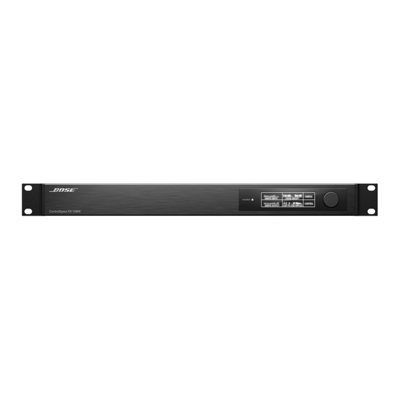
TROUBLESHOOTING 1. When the EX-1280C is first powered up and fully booted, you should see the display below on the front panel. This panel indicates the firmware versions for all of the installed PCB’s. If you cannot see a firmware version for a particular PCB, that means that the unit’s firmware is not seeing that board and may indicate a fault with that particular board. - Page 118 TROUBLESHOOTING (CONT.) Problem What to do Power LED • Most often the result of a design file/firmware mismatch. remains red after • If necessary, retrieve saved design from the EX-1280C, then send a blank design to the EX- booting 1280C. The LED should change to white. •...
-
Page 119: Service Manual Revision History
SERVICE MANUAL REVISION HISTORY Revision Change Driven Date Description of Change Page(s) Affected Level 12/21/2017 Document released at revision 00 Initial Release... - Page 120 Bose Corporation 100 The Mountain Road Framingham Massachusetts USA 01701 Reference Number 772234-SM REV 00; 12/2017 http://serviceops.bose.com...
Need help?
Do you have a question about the ControlSpace EX-1280C and is the answer not in the manual?
Questions and answers