Bose ControlSpace SP-24 Service Manual
Hide thumbs
Also See for ControlSpace SP-24:
- Quick start manual (2 pages) ,
- Installation and operating manual (40 pages) ,
- Quick start manual (2 pages)

Related Manuals for Bose ControlSpace SP-24


Summary of Contents for Bose ControlSpace SP-24
- Page 1 ® ControlSpace SP-24 Sound Processor (US and non-US units) ©2012 Bose Corporation Service Manual Reference Number 352427-SM Rev. 00...
-
Page 2: Table Of Contents
Packaging Part List, ControlSpace SP-24 Sound Processor (see Figure 1) ......12 Figure 1. ControlSpace SP-24 Sound Processor Packaging View ..........12 Main Part List, ControlSpace® SP-24 Sound Processor (see Figure 2) ......13-14 Figure 2. ControlSpace SP-24 Sound Processor Exploded View ........... 14 Main Part List, Front Panel Sub-assembly (see Figure 3) ............ -
Page 3: Safety Information
THE PURPOSE OF SERVICING THE IDENTIFIED BOSE PRODUCT BY AN AUTHORIZED BOSE SERVICE CENTER OR OWNER OF THE BOSE PRODUCT, AND SHALL NOT BE REPRODUCED OR USED FOR ANY OTHER PURPOSE. WARRANTY The Bose ControlSpace SP-24 sound processor is covered by a limited 5-year transferable limited warranty. -
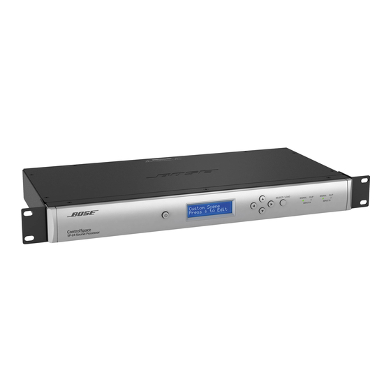
Page 4: Product Description
ControlSpace SP-24 Editor User’s Guide (PDF) This document provides detailed instructions on how to use ControlSpace SP-24 Editor software to fully configure and update the unit. The most current version of this guide can be downloaded from pro.Bose.com and is included in the software help file. - Page 5 Note: Use of docking stations or USB hubs is not recommended. SP-24 Editor SP-24 Editor soft software Note: The SP-24 Editor software and User’s Guide are available for download from pro.Bose.com. System Requirements The following are the minimum system requirements for the SP-24 Editor software: • Microsoft ®...
- Page 6 For additional information related to the set up and configuration via the SP-24 Editor software, see the SP-24 Editor software User’s Guide available at pro.Bose.com. Note: The SP-24 Editor software requires the use of a PC running Windows XP or Windows 7 and an available USB port.
- Page 7 Factory Fixed Routing Table The loudspeaker Presets are linked to pre-defined modes for common configurations of current Bose loudspeakers. Discontinued Bose loudspeaker EQs can be loaded and applied via the SP-24 Editor software. The following table indicates how each Preset mode affects input channel routing and filtering at each of the four output channels.
- Page 8 SP-24 sound processer can be updated using the ControlSpace SP-24 Editor software. To obtain the newest versions of firmware and EQ files, go to pro.Bose.com. For more information about updating the firmware and loudspeaker EQ Presets, please refer to the ControlSpace...
- Page 9 Custom Scenes and store them within the processor. Up to four Custom Scenes may be stored to the SP-24 processor. Additional information on the design and configuration of systems using the ControlSpace SP-24 sound processor can be found at pro.Bose.com.
-
Page 10: Specifications
SPECIFICATIONS Aud io Perfo rmance Specifications Fre quency Response 20 Hz - 20 k Hz (+0/-1 dB) THD+N 0.003% (t ypical) Channe l Se paration (Crosstalk) 100 dB (typical) Dynamic R ange 103 dB (typical) Integrated DSP Audio Lat ency 1.52 ms A/D and D/A Converters 24-bit... -
Page 11: Electrostatic Discharge Sensitive (Esds) Device Handling
ELECTROSTATIC DISCHARGE SENSITIVE (ESDS) DEVICE HANDLING This unit contains ESDS devices. We recommend the following precautions when repairing, replacing or transporting ESDS devices: • Perform work at an electrically grounded work station. • Wear wrist straps that connect to the station or heel straps that connect to conductive floor mats. -
Page 12: Packaging Part List, Controlspace
POLY BAG , OWNER’S MANUAL, 10'*14' 1497-4122+0 W/ES GREEN CARTON 354534-0010 1480-9502+1 PACKING, POLYFOAM 298163 1490-4621+1 POLYBAG USB A TO B, CORD, UL2725, 2 M 354117-0010 7013-2490+0 POLY BAG, USB CORD, 10'*14' W/ES 1497-4122+0 Figure 1. ControlSpace SP-24 Sound Processor Packaging View... -
Page 13: Main Part List, Controlspace® Sp-24 Sound Processor (See Figure 2)
MAIN PART LIST ControlSpace ® SP-24 Sound Processor (see Figure 2) ® Item Description Bose Part Vendor Part Qty. Note Number Number Number SCREW, MACHINE, CS, M3X6 2901-3005+3000 COVER, TOP 298519 1405-9901+0 FRONT PANEL ASSEMBLY, 354125-001S SVC- CONSISTS OF ITEMS 3 – 10... - Page 14 2705-0060+0 3, 4 FP63.5X12.7X28.5 CABLE, CLAMP, SELF-ADHESIVE, 6360-9750+0 21.5X21.5 CABLE, IDC, 24P, L=110, 3501 7012-7520+0 SERIES CABLE, IDC, 30P, L=100, 3501 7012-7531+0 SERIES WIRE, CONN, 16P, P2.0, #28, 7012-7641+0 UL2651, L=200, FEMALE Figure 2. ControlSpace SP-24 Sound Processor Exploded View...
-
Page 15: Main Part List, Front Panel Sub-Assembly (See Figure 3)
MAIN PART LIST Front Panel Sub-assembly (see Figure 3) ® Item Description Bose Part Vendor Part Qty. Note Number Number Number FRONT PANEL SUBASSEMBLY 354125-001S SVC- CONSISTS OF: BASIC14+FPSP COVER, FRONT, ALUMINUM 353809-0010 1405-9901+0 PANEL, FRONT 1467-6801+0 LED LIGHT PIPE... -
Page 16: Electrical Part Lists
ELECTRICAL PART LIST Digital Signal Processor (DSP) PCB Assembly Resistors Reference Description Vendor Part Note Designator Number R101 RCFA, 33RX4, 1/16W, 5%, 0603 4703-330J+P-04 R102 RCFA, 220RX4, 1/16W, 5%, 0603 4703-221J+P-04 R103 RCFA, 33RX4, 1/16W, 5%, 0603 4703-330J+P-04 R104 RCFA, 33RX4, 1/16W, 5%, 0603 4703-330J+P-04 R105 RCFA, 33RX4, 1/16W, 5%, 0603... - Page 17 ELECTRICAL PART LIST Digital Signal Processor (DSP) PCB Assembly Resistors (continued) Reference Description Vendor Part Note Designator Number R522 1.1K, RMG, 1/16W, 1%, 0603, 4723-112A+P R523 1.1K, RMG, 1/16W, 1%, 0603, 4723-112A+P R524 1K, RMG, 1/16W, 1%, 0603/1608 4723-102A+P R525 2.2K, RMG, 1/16W, 1%, 0603/1608 4723-222A+P R526...
- Page 18 ELECTRICAL PART LIST Digital Signal Processor (DSP) PCB Assembly Capacitors Reference Description Vendor Part Note Designator Number C500 0.1uF, CC, 50V, 10%, 0603/1608, 1x2 150F-104K+P-AC C501 0.1uF, CC, 50V, 10%, 0603/1608, 1x2 150F-104K+P-AC C502 0.1uF, CC, 50V, 10%, 0603/1608, 1x2 150F-104K+P-AC C503 0.1uF, CC, 50V, 10%, 0603/1608, 1x2...
- Page 19 ELECTRICAL PART LIST Digital Signal Processor (DSP) PCB Assembly Capacitors (continued) Reference Description Vendor Part Note Designator Number C554 0.1uF, CC, 50V, 10%, 0603/1608, 1x2 150F-104K+P-AC C555 0.1uF, CC, 50V, 10%, 0603/1608, 1x2 150F-104K+P-AC C556 0.1uF, CC, 50V, 10%, 0603/1608, 1x2 150F-104K+P-AC C557 1UF, CC, 50V, +80/-20%, 0805...
- Page 20 ELECTRICAL PART LIST Digital Signal Processor (DSP) PCB Assembly Capacitors (continued) Reference Description Vendor Part Note Designator Number CT518 1UF, CT, 16V, 20%, SM, 1.6X3.2 154D-106M+3-CF CT519 1UF, CT, 16V, 20%, SM, 1.6X3.2 154D-106M+3-CF CT521 1UF, CT, 16V, 20%, SM, 1.6X3.2 154E-106M+3-FK CT522 1UF, CT, 16V, 20%, SM, 1.6X3.2...
- Page 21 ELECTRICAL PART LIST Digital Signal Processor (DSP) PCB Assembly Integrated Circuits Reference Description Vendor Part Note Designator Number U500 FLASH, MX29LV400CBTI-70G, TSOP48 3132-8111+0 U501 DSP, TMS320D708RFP, PQFP144 3132-8231+0 U502 PLD, EPM3064A-10, TQPF44, ALTERA 3132-3331+0 U503 SUPPLY, VOL, SUPERVISOR, TL7705BCD, SOP-8, TI 3132-3401+0 U504 LOW-DROP, LINEAR, REGU, TPS726126DCQ, SOT223-...
-
Page 22: Input/Output Pcb Assembly
ELECTRICAL PART LIST Input/Output PCB Assembly Resistors Reference Description Vendor Part Number Note Designator R318 10R, RMG, 1/16W, 5%, 0603/1608 4723-100J+P R506 22R, RMG, 1/16W, 5%, 0603/1608 4723-220J+P R507 22R, RMG, 1/16W, 5%, 0603/1608 4723-220J+P R514 0R, RMG, 1/16W, 5%, 0603 4723-000J+P R700 1K, RCF, 1/2W, 5%, AT... - Page 23 ELECTRICAL PART LIST Input/Output PCB Assembly Resistors (continued) Reference Description Vendor Part Number Note Designator R784 2K, RMG, 1/16W, 1%, 0603/1608 4723-202A+P R785 2.7K, RMG, 1/16W, 5%, 0603/1608 4723-272J+P R786 2.7K, RMG, 1/16W, 5%, 0603/1608 4723-272J+P R789 10K, RMG, 1/16W, 1%, 0603/1608 4723-103A+P R790 2.7K, RMG, 1/16W, 5%, 0603/1608...
- Page 24 ELECTRICAL PART LIST Input/Output PCB Assembly Capacitors (continued) Reference Description Vendor Part Number Note Designator C723 220pF, CC, 50V, 5%, 0603 150F-221J+P-AC C724 0.1uF, CC, 50V, 10%, 0603/1608, 1x2 150F-104K+P-AC C725 0.1uF, CC, 50V, 10%, 0603/1608, 1x2 150F-104K+P-AC C726 220pF, CC, 50V, 5%, 0603 150F-221J+P-AC C727 0.068uF, CC, 50V, 10%, 0603, 1x2...
- Page 25 ELECTRICAL PART LIST Input/Output PCB Assembly Capacitors (continued) Reference Description Vendor Part Number Note Designator CT708 10uF, CE, 25V, 20%, RLT, 5X11 157E-106M+K-IU CT717 100uF, CE, 25V, 20%, GS, RLT, 6.3X11 157E-107M+K-LUG CT718 100uF, CE, 25V, 20%, GS, RLT, 6.3X11 157E-107M+K-LUG CT719 100uF, CE, 25V, 20%, GS, RLT, 6.3X11...
- Page 26 ELECTRICAL PART LIST Input/Output PCB Assembly Transistors (continued) Reference Description Vendor Part Number Note Designator Q802 MOSFET, N-CH, 60V, 115MA, 2N7002, 4907-0020+3 SOT-23, SM Q803 MOSFET, N-CH, 60V, 115MA, 2N7002, 4907-0020+3 SOT-23, SM Q804 MPSA06, VCE, 80V, NS, RLT 4860-8890+K Q805 MPS, A56, VCE, 80V, NS, RLT 4860-8910+K...
-
Page 27: Button And Led Pcb Assembly
ELECTRICAL PART LIST Button and LED PCB Assembly Resistors Reference Description Vendor Part Note Designator Number 100R, RCF, 1W, 5%, AL 4708-101J+1 R101 470R, RMG, 1/16W, 1% 4723-471A+P R102 910R, RMG, 1/16W, 1%, 0603 4723-911A+P-R R103 270R, RMG, 1/16W, 1% 4723-271A+P R104 910R, RMG, 1/16W, 1%, 0603... -
Page 28: Switch Pcb Assembly
ELECTRICAL PART LIST Switch PCB Assembly Resistors Reference Description Vendor Part Note Designator Number R912 10R, RMG, 1/16W, 1%, 0603 4723-100A+P-R R911 1K, RMG, 1/16W, 1%, 0603/1608 4723-102A+P R913 1K, RMG, 1/16W, 1%, 0603/1608 4723-102A+P R910 30K, RMG, 1/16W, 1%, 0603/1608 4723-303A+P Capacitors Reference... -
Page 29: Electrical Part List
ELECTRICAL PART LIST Switch Mode Power Supply (SMPS) PCB Assembly Resistors Reference Description Vendor Part Note Designator Number 0 OHM, 0805, SMD, +/-5% 15B-000J81 1M, 1206, SMD, +/-5% 15S-105J41 3, 4 1M, 1206, SMD, +/-5% 15S-105J41 3, 4 2M, 1206, SMD, +/-5% 15S-205J41 2M, 1206, SMD, +/-5% 15S-205J41... - Page 30 ELECTRICAL PART LIST Switch Mode Power Supply (SMPS) PCB Assembly Capacitors (continued) Reference Description Vendor Part Note Designator Number 222M, 1KV, PIN=5 17C-222KLA 22uF, 50V, 5x11, +/-20% 17A-220M7B 100nF, 50V, 1206, X7R 17S-104M72 68pF, 50V, 0805, X7R 17B-680J71 1nF, 0805, SMD, 50V, X7R 17B-102K71 1nF, 1206, SMD, 250V, X7R 17S-102KD1...
- Page 31 ELECTRICAL PART LIST Switch Mode Power Supply (SMPS) PCB Assembly Inductors Reference Description Vendor Part Note Designator Number 25mH (Vdson (HZ) Electronics Co. model UD0880 3, 4 VD0880) 22Uh GL0603-220J 4.7uH, 3A DR0710-4R7M-D180 4.7uH, 3A DR0710-4R7M-D180 10uH, 1A DR0608-100M-D182 3.3uH, 3A ISO-359K01-L01 Diodes Reference...
- Page 32 ELECTRICAL PART LIST Switch Mode Power Supply (SMPS) PCB Assembly Integrated Circuits Reference Description Vendor Part Note Designator Number NCP1200DR2, f=60KH, SOP-8 11S-P1200G KIA431B, 2.5V +/-1%, T0-220, KEC 11W-A431BA LM7812, 12V, T0-220, FAIRCHILD 11W-M7812B KA7912, 12V, T0-220, FAIRCHILD 11W-A7912B LDO, LM1084, 5V, T0-220, FAIRCHILD 11W-N1084B LDO, LM1084, 5V, T0-220, FAIRCHILD 11W-N1084B...
-
Page 33: Disassembly Procedures
DISASSEMBLY PROCEDURES Note: Refer to the photos at right for the following procedures. CAUTION: Be sure AC mains power is removed before disassembling the unit. 1. Top Cover Removal 1.1 Remove the nine screws as shown at right. Lift up the back edge of the top cover and slide it off the chassis. - Page 34 DISASSEMBLY PROCEDURES 3.4 Remove the twelve screws that secure the XLR jacks to the back of the chassis. Remove the one screw that secures the USB connector to the chassis. 3.5 Remove the two screws (4) that secure the Input / Output PCB (2) to the chassis. 3.6 Slide the I/O PCB toward the front of the chassis and lift it out.
- Page 35 DISASSEMBLY PROCEDURES 6. Display PCB Removal 6.1 Perform procedure 1. 6.2 Unplug the Display PCB’s ribbon cable from the Button/LED PCB at J303. 6.3 Using a right-angle Phillips-head screw- driver, remove the four screws that secure the Display PCB to the plastic front panel. 6.4 Lift out the Display PCB.
- Page 36 DISASSEMBLY PROCEDURES 8.3 Disconnect the green/yellow ground wire that is secured at the corner of the power supply. That wire connects to the bottom edge of the front panel metal wrap. 8.4 Using a small flat-tip screwdriver, release the nine plastic tabs that secure the front panel to the chassis.
-
Page 37: Test Procedures
Apply AC mains voltage to the unit and verify • ® SP-24 ControlSpace Editor software the idle current as follows: (can be downloaded from Max Current http://pro.bose.com) 120VAC/60Hz 120 mA General Test Configuration 240VAC/50Hz 100 mA 100VAC/60Hz 150 mA •... - Page 38 TEST PROCEDURES 4.3 Increase the input level to +18 dBu. Verify 8. Signal To Noise Test that the Signal 1 and Signal 2 LED’s remain GREEN and that the Clip 1 and Clip 2 LED’s 8.1 Terminate all inputs with 600 Ohms, each remain OFF.
- Page 39 TEST PROCEDURES 10. Crosstalk Test 13. Turn-off Pop Test 10.1 Apply a 1 kHz, 0 dBu sine wave into 13.1 Turn the unit OFF by pressing the input A or B only. Using a 1 kHz band reject power switch on the front panel. Verify that filter, measure the signal level in dB at the there is no audible off-pop when connected outputs specified below.
- Page 40 TEST PROCEDURES Hi-Pot tester settings: If the ground connection from the AC inlet to the chassis needed to be disconnected as IMPORTANT: part of the repair, then the unit would also The SP-24 Sound Processor needs to be need the Ground Bond test below. tested using two different settings as shown below.
-
Page 41: Upgrading The Controlspace Sp-24 Firmware
Upgrading the ControlSpace SP-24 Firmware The ControlSpace SP-24 firmware and EQ presets can be updated by using the SP-24 Editor software, and connecting the SP-24 unit to the PC using a USB A to B cable. Download the application update installer to your PC and install it. The SP-24 Editor software application can be downloaded from the http://pro.bose.com web site. - Page 42 ® Upgrading the ControlSpace SP-24 Firmware 2. Launch the SP-24 Firmware update application and follow the on-screen steps to install the updated SP-24 firmware and/or loudspeaker database update. 3. Once the installation is complete, click ‘Finish’ to close the installer. You are now ready to upgrade the firmware within the SP-24 sound processor.
- Page 43 ® Upgrading the ControlSpace SP-24 Firmware 5. Pressing 'OK' causes the File Open dialog to appear. Select the new firmware file that will be uploaded to the processor. 6. You will be prompted to Erase all settings from the processor. 7.
-
Page 44: Upgrading The Bose Loudspeaker Eq Database
Upgrading the Bose Loudspeaker EQ Database As new loudspeaker products become available from Bose professional systems we will issue a loudspeaker database only firmware update. The most recent loudspeaker EQ database update for the SP-24 sound processor is always available at http://pro.Bose.com. All loudspeaker database and firmware updates are provided using an application update installer. - Page 45 ® Upgrading the Bose Loudspeaker EQ Database 4. Clicking ‘OK’ causes the File Open dialog to appear. Select the new loudspeaker EQ database file that will be uploaded to the processor. 5. Once the firmware update process has begun the firmware update progress dialog appears.
-
Page 46: Upgrading An Existing Psdc I Or Ii Based System To The Sp-24 Sound Processor
Bose loudspeaker products. The following legacy equalization curves are available: BOSE Pro f e ssi o n a l Le gacy Equali za t i o n Cu r v e s Fr ee Spa ce... -
Page 47: Controlspace Sp-24 Block Diagram
® ControlSpace SP-24 Block Diagram... -
Page 48: Service Manual Revision History
Service Manual Revision History Date Revision Description of Change Change Driven Pages Level Affected 7/12 Document released at revision 00. Service manual release... - Page 49 SPECIFICATIONS AND FEATURES SUBJECT TO CHANGE WITHOUT NOTICE Bose Corporation The Mountain Framingham Massachusetts USA 01701 P/N: 352427-SM Rev. 00 7/2012 (P) http://serviceops.bose.com...
Need help?
Do you have a question about the ControlSpace SP-24 and is the answer not in the manual?
Questions and answers