
Related Manuals for ACME Theatre Spot 150


Summary of Contents for ACME Theatre Spot 150
- Page 1 TS-150 CW TS-150 WW TS-150 WW W TS-1504 CW TS-1504 WW User Manual Please read the instruc on carefully before use...
-
Page 2: Table Of Contents
CONTENTS 1. Safety Instructions ................. 2 2. Technical Specifications ................. 3 3. The Plate for Color Filter & Barn Door Installation ......... 5 4. How To Set The Unit................6 4.1 Control panel ................... 6 4.2 Main Functions ................7 5. -
Page 3: Safety Instructions
1. Safety Instructions Please read the instruction carefully which includes important information about the installation, usage and maintenance. WARNING Please keep this User Guide for future consultation. If you sell the unit to another user, be sure that they also receive this instruction manual. ... -
Page 4: Technical Specifications
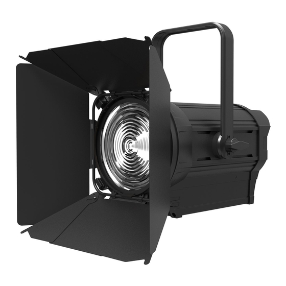
moisture. DO NOT open the unit within five minutes after switching off. The housing, the lenses, or the ultraviolet filter must be replaced if they are visibly damaged. Caution There are no user serviceable parts inside the unit. DO NOT open the housing or attempt any repairs yourself. - Page 5 ◆ TS-150 WW/CW with Chinese Fresnel lens ◆ TS-1504 WW/CW with German Fresnel lens Power supply: AC 100~240V, 50/60Hz Power consumption: 190W Color Temperature: 5600+100K (TS-150 CW) 3150+100K (TS-150 WW) Light Source: 1 × 150W white LED CRI: ...
-
Page 6: The Plate For Color Filter & Barn Door Installation
3. The Plate for Color Filter & Barn Door Installation Fig. 1 ○ At first, please push the Lock Cap button by hand as the arrow , and move away the Lock as the ○ ○ arrow ; Then insert the Plate for Color Filter into the inside slot from topside Fig. -
Page 7: How To Set The Unit
4. How To Set The Unit 4.1 Control panel 1. Display: Show the various menus and the selected functions. 2. LED: MASTER Master Mode SLAVE Slave Mode DMX input present 3. Button: MENU To select the programming functions DOWN To go backward in the selected functions To go forward in the selected functions ENTER To confirm the selected functions... -
Page 8: Main Functions
4. Dimmer: Manual adjust the dimmer value. 5 Zoom: Manual adjust the zoom value. 6. DMX input: For DMX512 link, use 5-pin XLR cable to link the unit together. 7. POWER IN: Connects to mains supply power. 8. POWER OUT: Connects to the next unit. 9. - Page 10 DMX Setting Enter menu mode, select DMX Setting, press ENTER button to confirm, use UP/DOWN button to select DMX Address, Art-Net Setup or Channel Mode. Select DMX Address, press the ENTER button to confirm, the present address will blink on the display.
- Page 11 Square Law: Light intensity control is finer at low levels and coarser at high levels. Inverse Square Law: Light intensity control is coarser at low levels and finger at high levels. Linear: The increase in light intensity appears to be linear as DMX value is increased. S-cure: Light intensity control is finger at low levels and high levels and coarser at medium levels.
- Page 12 display, use the UP/DOWN button to adjust value from 1 to 30, press the ENTER button to save. Press the MENU button back to the last menu or let the unit idle one minute to exit menu mode. Backlight Auto Off Select Backlight Auto Off, press the ENTER button to confirm, present mode will blink on the display, use the UP/DOWN button to select Yes (display goes off one minute after exiting menu mode) or No (display always on), press the ENTER button to save.
-
Page 13: How To Control The Unit
on the display. Press the MENU button back to exit. Factory Setting Select Factory Setting, press the ENTER button to confirm, present mode will blink on the display. Use the DOWN and UP button to select the No or Yes (Switch back to default settings). Hold and press the MENU button about one second or wait for one minute to exit the menu mode. -
Page 14: Dmx 512 Configurations
Channel Unit 1 Unit 2 Unit 3 Unit 4 mode Address Address Address Address 2 Channels 3 Channels 5.3 DMX 512 Configurations 2 Channels Mode: CHANNEL VALUE FUNCTION DIMMER 0 ~ 255 0 100% 0 ~ 255 ZOOM 3 Channels Mode: CHANNEL VALUE FUNCTION... -
Page 15: Troubleshooting
1. Connect the fixture together in a “daisy chain” by XLR plug cable from the output of the fixture to the input of the next fixture. The cable cannot be branched or split to a “Y” cable. Inadequate or damaged cables, soldered joints or corroded connectors can easily distort the signal and shut down the system 2. -
Page 16: Fixture Cleaning
DMX polarity. 3. If you have intermittent DMX signal problems, check the pins on connectors or on PCB of the unit or the previous one. 4. Try to use another DMX controller. 5. Check if the DMX cables run near or run alongside to high voltage cables that may cause damage or interference to DMX interface circuit. - Page 19 D eclaration of Conformity We declare that our products (lighting equipments) comply with the following specification and bears CE mark in accordance with the provision of the Electromagnetic Compatibility (EMC) Directive 89/336/EEC. EN55103-1: 2009 ; EN55103-2: 2009; EN62471: 2008; EN61000-3-2: 2006 + A1:2009 + A2:2009; EN61000-3-3: 2008. &...
- Page 20 Innovation, Quality, Performance...
Need help?
Do you have a question about the Theatre Spot 150 and is the answer not in the manual?
Questions and answers