Sungrow SG6600UD-MV System Manual
Mv grid-connected inverter
Hide thumbs
Also See for SG6600UD-MV:
- User manual (18 pages) ,
- User manual (146 pages) ,
- Installation manual (21 pages)
Table of Contents
Advertisement
Advertisement
Table of Contents

Related Manuals for Sungrow SG6600UD-MV


Summary of Contents for Sungrow SG6600UD-MV
- Page 1 System Manual MV Grid-Connected Inverter SG6600UD-MV/SG6600UD-MV-20/ SG8800UD-MV/SG8800UD-MV-20 SG6600UD-MV/SG6600UD- MV Grid- MV-20/SG8800UD-MV/SG8800UD-MV-20 Connected InverterSystem ManualSG6600_8800UD-MV–20- SEN-Ver24–202404M-D-000537 SG6600_8800UD-MV–20-SEN-Ver24–202404...
-
Page 3: All Rights Reserved
Software Licenses • It is prohibited to use data contained in firmware or software developed by SUNGROW, in part or in full, for commercial purposes by any means. • It is prohibited to perform reverse engineering, cracking, or any other operations that... -
Page 5: Table Of Contents
Contents All Rights Reserved .....................I 1 About This Manual ...................1 1.1 Validity......................1 1.2 Target Group ....................1 1.3 How to Use This Manual .................1 1.4 Symbol Explanations ..................2 2 Safety Instructions ....................3 2.1 Unpacking and Inspection ................4 2.2 Hoisting and Transportation................5 2.3 Electrical Connection ..................5 2.4 Operation.......................7 2.5 Operation and Maintenance ................7... - Page 6 5.2 Inspection Before Installation.................21 5.2.1 Scope of Delivery ................21 5.2.2 Product Inspection ................22 5.3 Installation Environment Requirements ............22 5.3.1 Installation Site ...................22 5.3.2 Foundation ..................22 5.3.3 Installation Spacing ................23 5.4 Hoisting and Fixing ..................23 5.4.1 Preparation Before Hoisting ..............23 5.4.2 Requirements for hoist and lifting rope ..........24 5.4.3 During Hoisting ...................24 5.4.4 Fastening of Connectors..............25 5.4.5 Fixing ....................26...
- Page 7 6.7.2 Procedure ..................47 6.8 Switch/Ethernet Communication ..............47 6.9 Check After Wiring..................48 6.9.1 Inspection ..................48 6.9.2 Locking Cabinet Door ................49 7 Powering up and Powering down ..............50 7.1 Safety Instructions ..................50 7.2 Powering Up Operations ................50 7.2.1 Removing Film on Product..............50 7.2.2 Removing Pressure Relief Screw ............51 7.2.3 Installing Fuse in AC SPD ..............51 7.2.4 Adjusting De-energized Tap Changer ...........52...
- Page 8 8.4.6 Setting Operation Parameters ..............62 8.4.7 Setting Protection Parameters..............62 8.5 Modifying Password..................62 8.6 Logout ......................62 9 O&M on iSolarCloud App ................63 9.1 About iSolarCloud ..................63 9.2 Function Overview..................63 9.3 Download and Installation ................63 9.4 Login ......................64 9.4.1 Requirements ..................64 9.4.2 Login Steps ..................65 9.5 Home ......................68 9.6 Run Information....................70 9.7 Records .......................71...
- Page 9 11.3.5.2 Indelible Traces ...............98 11.3.5.3 Broken Primer................99 11.3.6 Checking Door Locks and Hinges ............. 100 11.3.7 Checking Sealing Strips ..............100 11.4 Replacing Fuse..................100 11.4.1 Replacing DC Side Fuse ..............100 11.4.2 Replacing Fuse Inside Power Distribution Cabinet ......101 11.5 Replacing Fans..................
-
Page 11: About This Manual
This manual describes the transportation and storage, mechanical installation, electrical connection, power up and shutdown, web operation, troubleshooting, and maintenance of the MV grid-connected inverter. Validity This manual applies to the following models: • SG6600UD-MV • SG8800UD-MV • SG6600UD-MV-20 •... -
Page 12: Symbol Explanations
1 About This Manual System Manual version upgrade, and the actual product shall prevail. For any questions, please contact Sungrow Customer Service. Symbol Explanations To ensure the safety of the users and their properties when they use the product and to make sure that the product is used optimally and efficiently, this manual provides users with the relevant safety information which is marked by the following symbols. -
Page 13: Safety Instructions
Level 6 or stronger winds. SUNGROW shall not be held liable for any damage to the device due to force majeure, such as... -
Page 14: Unpacking And Inspection
Perform operations considering ac- tual onsite conditions. • SUNGROW shall not be held liable for any damage caused by violation of gen- eral safety operation requirements, general safety standards, or any safety in- struction in this manual. -
Page 15: Hoisting And Transportation
System Manual 2 Safety Instructions Hoisting and Transportation Risk of personal injury or device damage due to incorrect operation! • Follow the procedure of work of heights when walking on the top of the product. • All hoisting and transportation must comply with the relevant codes and regula- tions of the nation/region where the project is located. - Page 16 2 Safety Instructions System Manual PV modules will generate lethal high voltage when exposed to sunlight. • Operators must wear proper personal protective equipment during electrical connections. • Before performing an electrical connection, be sure to disconnect the PVS and use measuring equipment to ensure that cables are voltage-free.
-
Page 17: Operation
System Manual 2 Safety Instructions Operation When the product is working, • It is strictly forbidden to touch the live parts of the product. Otherwise, an elec- tric shock may occur. • It is strictly prohibited to disassemble any parts of the product. Otherwise, an electric shock may occur. - Page 18 To avoid the risk of electric shock, do not perform any other maintenance opera- tions beyond those described in this manual. If necessary, contact SUNGROW for maintenance. Otherwise, the losses caused are not covered by the warranty.
-
Page 19: Disposal
System Manual 2 Safety Instructions Disposal Please scrap the inverter in accordance with relevant local regulations and stand- ards to avoid property losses or casualties. -
Page 20: Product Description
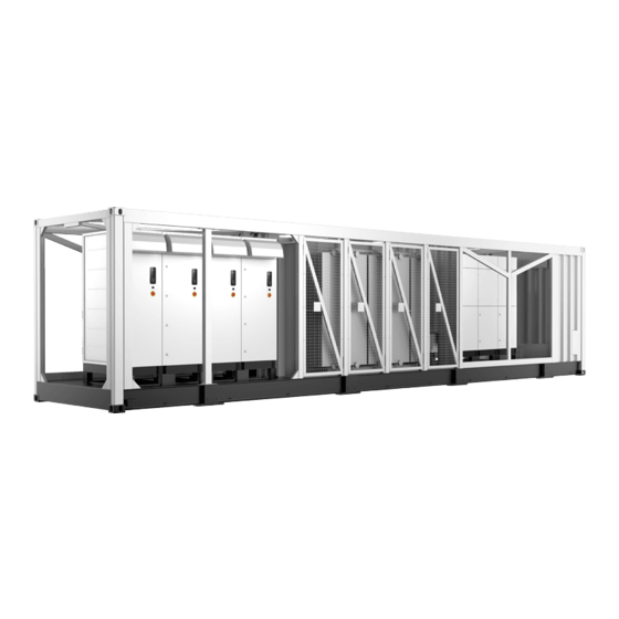
Product Description Product Introduction In large and medium-sized utility power plant systems, the MV grid-connected inverter, which contains multiple PV inverter units, transformers, and other equipment, provides a sound solution to convert the DC power generated by PV arrays into AC power, and feed it into the grid. - Page 21 System Manual 3 Product Description * The figure is for reference only. And the actual product received shall prevail. Name Description Switchgear Connecting the grid to the transformer. For communication and power distribution. Power distribution cabinet Convert the DC power generated by PV modules Inverter units into AC power.
-
Page 22: Main Internal Equipment
3 Product Description System Manual Main Internal Equipment 3.3.1 Appearance of Inverter Unit Name Top air inlet Indicator panel Start/Stop knob Emergency stop button. In case of emergency, press this button to open the AC circuit breaker and DC load switch. Base LED Indicator table 3-1 Indicator Status Description... -
Page 23: Internal Structure Of Inverter Unit
System Manual 3 Product Description Description Color Status A fault occurred and the system cannot be con- Steady on nected to the grid for power generation. Blinking (Interval WiFi connection is established and data communi- 0.2s) cation is in process. A fault is detected. The AC and DC power are disconnected. -
Page 24: Main Parts Of Transformer
3 Product Description System Manual Description Name DC fuse DC wiring copper bar Fuse of AC side SPD Control the on/off of the AC side circuits of the AC circuit breaker QF1 inverter. Disconnect it before maintenance and repair. Maintenance switch QS3 Maintenance switch QS2 could also be located at the bottom left corner of the AC side. -
Page 25: Main Parts Of Power Distribution Cabinet
System Manual 3 Product Description Description Graphics Name When a fault occurs inside the transformer, a large amount of gas is generated, and the pressure of the insulating oil rises sharply. This valve automati- Automatic pres- cally opens to drain the oil when the pressure sure relief valve reaches the threshold, so that the internal pressure of the transformer can be rapidly reduced to a nor-... - Page 26 3 Product Description System Manual figure 3-1 Main Parts of 5K Power Distribution Cabinet Description Wiring terminal block and micro circuit breaker Fuse of power distribution cabinet SPD QS4, main switch Switch port Ethernet port Fuse of power distribution cabinet * is optional.
-
Page 27: Symbol On Products
System Manual 3 Product Description Description Fuse of power distribution cabinet Ethernet port Wiring terminal block and micro circuit breaker * The figure is for reference only. The product received may differ. * is optional. Symbol on Products Explanation Marks Comply with CE certification. -
Page 28: Transport And Storage
Transport and Storage Precautions Failure to transport and store the product in accordance with the requirements in this manual may invalidate the warranty. Transportation Requirements • Choose appropriate means of transportation according to the size and weight of the product. •... -
Page 29: Protection During Storage
• For a product shut down/stored for over six months, inspect its electrical components (IGBT module, switch, etc.), and take dehumidifcation and dedusting mesaures for the whole product. For detailed operation, please contact SUNGROW. -
Page 30: Mechanical Mounting
If there are prob- lems with the above inspection items, do not install the product and contact SUNGROW in time. -
Page 31: Inspection Before Installation
System Manual 5 Mechanical Mounting Improper hoisting may cause personal injury! • It is strictly prohibited to stand within 5m - 10m outside the operating area (i.e., under the boom and the hoisted machine) to avoid casualties. • Only professional personnel can operate the product, and be sure to wear per- sonal protective equipment when operating. -
Page 32: Product Inspection
• Visually check the product for any damage. If any problems are found or there is any question, please contact the forwarding company or SUNGROW. Only install the product when it is complete and intact. Before installation, ensure that: •... -
Page 33: Installation Spacing
System Manual 5 Mechanical Mounting • Pre-bury the threading pipe at the bottom of the foundation according to the location of the cable inlet holes at the bottom of the product. • A drainage system is necessary to prevent the bottom or internal equipment of the prod- uct from being soaked in water during the rainy season or during heavy rainfall. -
Page 34: Requirements For Hoist And Lifting Rope
5 Mechanical Mounting System Manual 5.4.2 Requirements for hoist and lifting rope Single cranes Two cranes Cranes Rated load 100t. Each hoist bears at least 50t. Two ropes of equal length and not Four sling ropes of equal length, less than 5m, or 4 ropes of equal the length of a single rope is not length and no less than 2.5m can be less than 13m. -
Page 35: Fastening Of Connectors
System Manual 5 Mechanical Mounting figure 5-2 Hoisting by One Crane figure 5-3 Hoisting by Two Cranes Be sure to hoist the product smoothly and evenly to avoid collision and vibration. Do not turn the product upside down, nor hoist it for a long time. Otherwise, per- sonal injury or product damage may occur! 5.4.4 Fastening of Connectors Use slings with hooks or U-hooks to hoist the MV Station. -
Page 36: Fixing
• National and local safety rules should be observed at all times. • Regardless of relevant safety rules may void pertinent warranty claims from Sungrow. 5.4.5 Fixing Hoist the product to the intended location and fix it. Fixed by Welding Secure the bottom of the product to the foundation by welding. -
Page 37: Installing Oil-Water Separator(Optional)
System Manual 5 Mechanical Mounting The steps to fixing the L mounting parts is shown in the following figure. 5.4.6 Installing Oil-Water Separator(Optional) Generally, if there is no external oil tray, the base of the product is used as an oil tray, and the installation position of the oil-water separator is reserved at the bottom of the product, as shown in figure A below. - Page 38 There are two oil-water separator installation positions reserved at the bottom of the product, one is connected to the oil-water separator, and the other installation position needs to be blocked with a plug. If the installation of the oil-water separator is needed, please contact SUNGROW customer service.
-
Page 39: Electrical Connection
Electrical Connection Precautions • Before electrical connections, please make sure that the inverter is not dam- aged, otherwise, it may cause danger! • Before electrical connections, please make sure that the product switch and all switches connected to the product are set to "OFF", and use measuring equip- ment to ensure that there is no voltage at the connection. -
Page 40: Wiring Overview
6 Electrical Connection System Manual Damage to the device caused by incorrect wiring is not covered by the warranty. • Electrical connection must be performed by professional personnel who wear personal protective equipment. • The cables used in the PV generation system must be firmly connected, in good condition, and well insulated to appropriate sizes. -
Page 41: Preparation Before Wiring
System Manual 6 Electrical Connection 1- Inverter 2– Transformer 3– Power Distribution Cabinet table 6-1 Interface Description Description Recommended Cable Specifications DC input port 400 mm at most AC output port 70 mm — 400 mm 2 x 0.75 mm —2 x 1.5 mm shielded twisted pair Communication port... - Page 42 6 Electrical Connection System Manual Heat gun Torque screwdriver Wire stripper Hydraulic clamp Torque wrench Multimeter Electric drill Screwdriver Protective gloves Goggles Insulated shoes Protective clothing Hard hat...
-
Page 43: Open The Product Door
System Manual 6 Electrical Connection 6.3.2 Open the Product Door Step 1 Remove the vertical beams and inclined beams around the product. Step 2 Open the cabinet door. Step 3 Fix the doors of the inverter unit cabinet and power distribution cabinet. Step 4 Remove the protective cover of the wiring area. -
Page 44: Position Of Cable Inlet
6 Electrical Connection System Manual • Select cables with a proper diameter according to the maximum load, and the cables should be long enough. • All DC input cables must be of the same specifications and materials. • AC output cables of three phases must be of the same specifications and materials. •... - Page 45 System Manual 6 Electrical Connection Step 3 Lead cables into the cabinet through the holes, then secure the cables. Cables can be se- cured in different ways, usually with fireproof mud and waterproof connectors. Generally, you can choose one of them to secure the cables on site. The figure below shows how to secure the cables with fireproof mud.
-
Page 46: Ground Connection
SUNGROW. * Waterproof connectors and fireproof mud used to secure the cables are optional. Please contact SUNGROW if you have the need. After wiring, seal off the cable inlet holes by filling the gaps around the cables with fireproof/waterproof materials such as fireproof mud to prevent the ingress of for- eign matter or moisture, thus avoiding affecting the product's long-term operation. -
Page 47: Overview
AC cables, DC cables, and communication cables. • Both grounding terminals on the side of the product must be connected to the protective grounding points reliably. SUNGROW shall not be held liable for any damage caused by the violation. Note the following during ground connection: •... -
Page 48: Grounding Cable
6 Electrical Connection System Manual 6.4.3 Grounding Cable Use 50 mm ~ 95mm grounding cables to reliably connect the two grounding terminals to the grounding points of the system. 1: Heat shrink tubing 2: OT/DT terminal DC Input Connection The PV string will generate lethal high voltage when exposed to sunlight. Respect all safety instructions listed in relevant documents about PV strings. -
Page 49: Overview
System Manual 6 Electrical Connection • Make sure the PV array is well insulated to the ground before connecting it to the inverter. • Make sure the maximum DC voltage and the maximum short circuit current of any string never exceed inverter permitted values specified in "Technical Parameters". - Page 50 6 Electrical Connection System Manual Floating Grounding figure 6-6 7–way DC Input figure 6-7 7–way DC input With MPLC Illustrations in the manual are for the product with 7 DC inputs only. • For the product with 6 DC inputs, in its DC wiring area, the first fuse and cop- per bar on the right in the illustration are removed.
-
Page 51: Installing Insulation Board Before Connection
System Manual 6 Electrical Connection figure 6-8 7–way DC input With ESS For the product with 6 DC inputs with ESS, in its DC wiring area, the first fuse and copper bar on the left in the illustration are removed. * The wiring area is subject to the actual product. -
Page 52: Procedure
6 Electrical Connection System Manual - - End * The figure is for reference only. The product received may differ. 6.5.3 Procedure Step 1 Lead the cable into the wiring area through the inlet hole, and mark the cable polarity. Step 2 Strip the protective layer of the cable to expose the copper core of the wire with strippers. - Page 53 System Manual 6 Electrical Connection Step 4 Secure the OT/DT terminal to the copper bar by M16 x 45 bolts with a tightening torque of 119- 140 N.m. • If copper wires are used, fasten the bolt assembly as shown below. figure 6-9 Copper Wire Connection •...
-
Page 54: Securing Cables
6 Electrical Connection System Manual Step 5 Pull the cable back slightly after wiring to ensure that the cable is long enough. • Ensure that the selected terminal can directly contact the copper bar. If there are any problems, contact the terminal manufacturer. •... -
Page 55: Ac Side Connection
System Manual 6 Electrical Connection * The figure is for illustration only and the actual product on site may be different. Description Cable Waterproof connector * Cable clip * Cables can be secured in different ways. In this figure, cables are secured with waterproof connectors, which is for illustration only. - Page 56 6 Electrical Connection System Manual Step 2 Prepare the terminals and install them tightly, where reference can be made to the cable connector installation manual. The wiring terminal can be connected with either copper cable or aluminium cable. • In case of copper cable, use copper wiring terminals. •...
-
Page 57: Communication Connection
System Manual 6 Electrical Connection Communication Connection 6.7.1 Overview There is an RS485 communication terminal block inside the power distribution cabinet. table 6-2 Port Mark and Definition (Example) Marks Plug-compatible Devices PVS, meteo station, electricity meter, transformer, etc. Reserved RS485 6.7.2 Procedure Take one cable as an example. -
Page 58: Check After Wiring
6 Electrical Connection System Manual figure 6-14 Ethernet Communication Port In 5K Power Distribution Cabinet figure 6-15 Ethernet Communication Port In 15K Power Distribution Cabinet Connect external monitoring devices to the Ethernet port by a CAT-5e cable. Check After Wiring 6.9.1 Inspection Check the wiring thoroughly and carefully when all electrical connections have been completed. -
Page 59: Locking Cabinet Door
System Manual 6 Electrical Connection 6.9.2 Locking Cabinet Door Step 1 Release the fixing doors of the inverter unit cabinet and the power distribution cabinet. Unfix in reverse of the fixing method, refer to "6.3.2 Open the Product Door". It is forbidden to close the door forcibly when the door is fixed. Step 2 Lock the cabinet door and pull out the key. -
Page 60: Powering Up And Powering Down
Powering up and Powering down Safety Instructions When the product is working: • It is strictly forbidden to touch the live parts of the product. Otherwise, an elec- tric shock may occur. • It is strictly prohibited to disassemble any parts of the product. Otherwise, an electric shock may occur. -
Page 61: Removing Pressure Relief Screw
System Manual 7 Powering up and Powering down figure 7-1 Remove Film from the Product Films Distribution Area of Power Distribution Cabinet figure 7-2 Remove Film at Air Inlet/Outlet of Power Distribution Cabinet * The figure is for reference only. And the actual product received shall prevail. 7.2.2 Removing Pressure Relief Screw Be sure to remove the pressure relief screws at the bottom of the inverter unit(marked as A in the figure below) before the product is officially put into operation. -
Page 62: Adjusting De-Energized Tap Changer
7 Powering up and Powering down System Manual Step 2 Insert fuses. Step 3 Close the fuse holder in the AC side SPD. - - End 7.2.4 Adjusting De-energized Tap Changer Adjust the output voltage of the transformer. When operating the de-energized tap changer, ensure that the transformer is in a non-excitation state, that is, the high and low voltage sides of the transformer are uncharged. -
Page 63: Opening Pressure Relief Valve
System Manual 7 Powering up and Powering down 7.2.5 Opening Pressure Relief Valve Open the cap on the pressure relief valve (marked as A below). 7.2.6 Removing Foam Part from Oil Thermometer Remove the protective cover on the oil thermometer and remove the foam parts in the pro- tective cover before the inverter is officially put into operation. -
Page 64: Inspection Before Powering Up
7 Powering up and Powering down System Manual Step 3 Remove the cover plate of the drain valve. Step 4 Open the drain valve and the oil in the transformer slowly flows from the transformer into the tank. Step 5 Check the position of the oil level gauge according to the temperature-level curve according to the local ambient temperature. -
Page 65: Pv Array
System Manual 7 Powering up and Powering down 7.3.2 PV Array The DC side voltage shall not exceed the maximum DC voltage allowed for the inverter. Oth- erwise, the inverter may be damaged and even cause safety accidents. To ensure the stable and efficient operation of the whole system, it is recommended that bat- teries connected to an inverter should be of the same type and from the same manufacturer, and the number of batteries connected in series should be the same. -
Page 66: Powering Down Operations
7 Powering up and Powering down System Manual Step 4 Check and ensure that the “Access Protection Enabling” switch is off on the Web interface. Step 5 Turn on the output switch of the upstream PVS. Step 6 Turn on the DC load switch QS1 inside all inverter units, and close the cabinet doors. Step 7 Rotate theSTART/STOP knob to theSTART position. - Page 67 System Manual 7 Powering up and Powering down Step 3 Open the AC cabinet door, check and ensure that the AC circuit breakers QF1 of all inverter units are all in the open state. Step 4 Turn off the maintenance switch QS2 of all inverter units, the maintenance switch QS3 at the bottom of the inverter unit, and the QS4 switch inside the power distribution cabinet.
-
Page 68: M On Web
O&M on WEB It is recommended to perform O&M on the WEB interface after the device is powered on. Communications Diagram The wiring between the internal devices of the MV grid-connected inverter has been com- pleted before delivery. Connect the PC with the switch inside the power distribution cabinet with the CAT-5e cable on site. -
Page 69: Preparation Before Login
SG-xxx (xxx represents the device SN), and enter the password. The password is ESPWifi@123. Step 2 Open a browser on the mobile phone and enter the address (11.11.11.1) or domain (sungrow. net) to access the WEB interface. - - End... -
Page 70: Login Steps
8 O&M on WEB System Manual Login Steps Step 1 Enter the server address to enter the homepage as a visitor by default. • NET1 port, URL: 12.12.12.12. • NET2 port, URL: 14.14.14.14. Mobile device: URL:11.11.11.1. Step 2 Click and select the desired language in the upper right corner of the interface. Step 3 Click to enter the login interface. -
Page 71: Viewing Fault Information
System Manual 8 O&M on WEB Description Language switching options User center 8.4.2 Viewing Fault Information Step 1 Click “Overview” → “General Information” on the left navigation bar to enter the homepage. Step 2 Click in the upper-right corner of the interface to view information such as the name and time of the fault event. -
Page 72: Setting Operation Parameters
8 O&M on WEB System Manual 8.4.6 Setting Operation Parameters Step 1 Click “Device Monitoring” in the left navigation bar. Step 2 Select a device in the left device list in the function display area. Click “Operation Parame- ters” on the right. enter a value in “Current Value”, and then click “Settings” Click “Configure Synchronization”to synchronize the settings to other devices of the same type. -
Page 73: M On Isolarcloud App
O&M on iSolarCloud App After the device is powered on, except on the Web interface, you can also perform simple O&M of devices on the iSolarCloud App. About iSolarCloud With iSolarCloud App, communication between the inverter and the mobile device can be established via WLAN, thus allowing for mobile maintenance of inverters. -
Page 74: Login
9 O&M on iSolarCloud App System Manual • Google Play (Android, users outside mainland China) • App Store (iOS) Option 2 Scan the QR code below, and download and install the App by following the onscreen instructions. Once installed successfully, the iSolarCloud icon will appear on the screen. Login 9.4.1 Requirements Before logging in to the App, please make sure:... -
Page 75: Login Steps
System Manual 9 O&M on iSolarCloud App 9.4.2 Login Steps Step 1 Turn on WLAN on your phone, search for the WLAN hotspot named “SG-A1234567890”, and enter the password to connect to the WLAN network. The default password is ESPWifi@123. •... - Page 76 9 O&M on iSolarCloud App System Manual Step 2 Open the iSolarCloud App. On the login screen, tap Local Access at bottom left. figure 9-2 Local Access Step 3 A confirmation dialog will pop up on the screen, which is shown below. Tap Confirm to con- nect to the device.
- Page 77 System Manual 9 O&M on iSolarCloud App figure 9-3 Login Confirmation Step 4 Tap More, and enter the account name and password to log in. The default account name is “user” and password is pw8888. Then, tap Verification. figure 9-4 Identity Verification To keep your account secure, please change the password as soon as possible.
-
Page 78: Home
9 O&M on iSolarCloud App System Manual Step 5 Once logged in, you will go to the Home screen of the App. - - End Home Once logged in, you will go to the Home screen, as shown below. - Page 79 System Manual 9 O&M on iSolarCloud App figure 9-5 Home Screen table 9-1 Description of Modules on the Home Screen Description Item Displays information such as generated output and feed-in power of the PV system are shown here. Arrows between the icons indicate that there is energy flowing between the devices.
-
Page 80: Run Information
9 O&M on iSolarCloud App System Manual Description Item Shows the daily yield curve by default. You can also switch to check the monthly, yearly, or total yield curve. The curves shown Data Curve here are based on power. Navigation Includes "Home", "Run Information", "Records", and "More". -
Page 81: Records
System Manual 9 O&M on iSolarCloud App table 9-2 Description of Run Information Description Item Data such as daily/monthly/annual yield, and DC/ac- Realtime Values tive/reactive power. Information related to Local Emergency Stop and MV Node Status node status, etc. Information such as the time of startup, and MPPT Operation Parameters voltage upper and lower limits. - Page 82 9 O&M on iSolarCloud App System Manual figure 9-7 Records Fault Alarm Record Tap Fault Alarm Record to check the fault alarm history, which is shown as follows. You can tap the drop-down arrow to the right of SG3300UD_UNIT1 and check the fault alarm re- cords of the inverter unit, whole inverter, or SCU as you want.
-
Page 83: More
System Manual 9 O&M on iSolarCloud App You can choose an item from the record list, and tap it to view its detailed information. More Tap More in the bottom navigation bar. Functions such as “Boot”, “Shutdown”, and “Modify Password” are available on this screen. figure 9-9 More 9.8.1 Boot/Shutdown You can choose Boot/Shutdown, and select a device to start/stop it. -
Page 84: Modify Password
9 O&M on iSolarCloud App System Manual 9.8.2 Modify Password You can choose“More→Modify Password” to change your password. The user interface is shown as follows. -
Page 85: Troubleshooting
Whether the emergency stop button is pressed • Whether the inverter limits the output of active power If the problem still persists or there are any other questions, please contact SUNGROW. It would be helpful if the following information is provided during a call: •... - Page 86 10 Troubleshooting System Manual Fault Name Fault Cause Fault Level Corrective Method 1. Check whether a short circuit occurs on the AC or DC sides of The drive board the inverter. generates a fault 2. Check the grid for any Important Module fault signal or a hard-...
- Page 87 System Manual 10 Troubleshooting Fault Name Fault Cause Fault Level Corrective Method 1. Check whether the grid volt- age is normal. 2. Check whether the control fan is normal. The temperature Control cabinet 3. Check the AC filter system. inside the control Important temperature Check whether there are abnor-...
- Page 88 10 Troubleshooting System Manual Fault Name Fault Cause Fault Level Corrective Method 1. Check whether the ambient temperature is normal; Use a thermometer to check whether the current ambient temperature is within the temper- ature range advertised by the If the temperature inverter.
- Page 89 System Manual 10 Troubleshooting Fault Name Fault Cause Fault Level Corrective Method 1 Check whether the protection parameters on the interface meet the grid standards of the lo- cation where the inverter is The grid fre- Frequency fault Important installed. quency is abnormal.
- Page 90 10 Troubleshooting System Manual Fault Name Fault Cause Fault Level Corrective Method Check whether the power grid is The inverter fails Important abnormal, such as harmonics Soft start fault to start. and voltage balance. Check the status indicator of the SPD.
- Page 91 System Manual 10 Troubleshooting Fault Name Fault Cause Fault Level Corrective Method Disconnect the DC switch of the inverter and check whether the open-circuit voltage of the PV ar- rays is normal; If not, the PV ar- ray configuration may be faulty. The DC side volt- 2.
- Page 92 10 Troubleshooting System Manual Fault Name Fault Cause Fault Level Corrective Method 1. Check the air inlet. 2. Check whether the air outlet The temperature of the inverter is blocked. Re- Module over- of modules inside place the air filter screen if Important temperature the inverter is ex-...
- Page 93 AC cabinet. Clean it if necessary. Check whether the DC fuse is The fuse on the blown. DC fuse Secondary DC side of the in- anomaly If so, please contact SUNGROW verter fails. to replace the fuse.
- Page 94 2. Check the communication ter- minal of the meter is loose. Check whether the DC fuse is The fuse on the blown. Secondary DC fuse fault DC side of the in- If so, please contact SUNGROW verter fails. to replace the fuse.
- Page 95 HVRT or LVRT. voltage. If the fault/alarm cannot be cleared following the above corrective methods and still persists, please contact SUNGROW directly. Fault Name Fault Cause Fault Level Corrective Method The AC switch is...
- Page 96 Fault Level Corrective Method The addresses of the inver- Machine code Please contact Important ter units inside the inverter repetition fault SUNGROW. are the same. Temperature and The communication of the humidity board Please contact Secondary temperature and humidity communication SUNGROW.
-
Page 97: Other Faults
If the fault is not caused by the fore- going reasons and still persists, please contact SUNGROW as soon as possible. 1. Refresh the Web page manually. 2. Restart or replace the mobile de-... - Page 98 Method”. If the fault is not caused by the fore- going reasons and still persists, please contact SUNGROW as soon as possible. 1. Export data in batches multiple The amount of data ex- Fail to export measur- times.
-
Page 99: Routine Maintenance
11 Routine Maintenance 11.1 Safety Instructions Risk of inverter damage or personal injury due to incorrect service! • Disconnect the switches between the product and all power supplies before maintenance. • After the inverter is powered off for 20 minutes, measure the voltage and cur- rent with measuring equipment. - Page 100 Otherwise, damage may be caused to the product! To avoid the risk of electric shock, do not perform any other maintenance opera- tions beyond those described in this manual. If necessary, contact SUNGROW for maintenance. Otherwise, the losses caused are not covered by the warranty.
-
Page 101: Maintenance Period
System Manual 11 Routine Maintenance 11.2 Maintenance Period 11.2.1 Maintenance (Once Every Three Years) Item Check method • Oil thermometer: Alarm temperature and tripping temperature. • Pressure relief valve: Check whether the pressure re- lief valve is in good contact. Monitoring and protective equipment of the transformer •... -
Page 102: Maintenance (Every Two Years)
11 Routine Maintenance System Manual 11.2.2 Maintenance (Every two years) Item Check method Check the following items, and correct immedi- ately those failing to meet the relevant requirements: • Check whether there is any damage or deforma- tion of the inverter and internal equipment. •... -
Page 103: Maintenance (Once A Year)
System Manual 11 Routine Maintenance 11.2.3 Maintenance (Once A Year) Item Check method Check the following items, and correct immediately those fail- ing to meet relevant requirements: • Check whether there are flammable objects on the top of the inverter. •... -
Page 104: Maintenance (Every Half A Year To Once A Year)
11 Routine Maintenance System Manual Item Check method • Check the running status of fans. • Check whether the fan blade rotates smoothly. • Check whether there is abnormal noise during the operation of the fans. Screw Check whether internal screws fell off. Check the following items, and correct immediately those fail- ing to meet relevant requirements: •... -
Page 105: Common Maintenance Items
System Manual 11 Routine Maintenance Item Check method Check the temperature of the heat sink and the amount of dust accumulated. Clean heat-dissipation modules with a vacuum Air inlet and outlet cleaner if necessary. • Carry out regular inspection for corrosion of all metal components. -
Page 106: Cleaning Air Outlet Of Inverter
11 Routine Maintenance System Manual Procedure Step 1 Use a screwdriver to remove the M5 fixing screws for the first maintenance. Step 2 Pull the spring plunger at both ends of the filter at the air inlet outward and tilt the filter down- ward to remove it. -
Page 107: Cleaning Air Inlet Of Power Distribution Cabinet
System Manual 11 Routine Maintenance Step 2 Clean the air outlets at the bottom of the AC side of the inverters. - - End 11.3.3 Cleaning Air Inlet of Power Distribution Cabinet Step 1 Remove the screws from the upper air inlet of the power distribution cabinet using a screwdriver. -
Page 108: Appearance Repair
11 Routine Maintenance System Manual - - End 11.3.5 Appearance Repair Check the appearance of the product: Check the appearance of the product: Case 1: Erasable traces Case 2: Indelible traces Case 3: Broken primer • Check whether the protective paint sprayed on the casing of the product fell off or peeled off. -
Page 109: Broken Primer
System Manual 11 Routine Maintenance Step 2 Wet the cleaning cloth with water or 97% alcohol, and scrub the damaged parts to remove surface stains. Step 3 Perform paint repair for the scratched parts with a soft brush after the surface is dried; brush the paint as uniform as possible. -
Page 110: Checking Door Locks And Hinges
11 Routine Maintenance System Manual Step 4 Perform paint repair for the damaged parts with a soft brush after the primer is dried, and brush the paint uniformly. - - End 11.3.6 Checking Door Locks and Hinges Check if the door locks and hinges of the inverter can be used normally after cleaning. Lubri- cate the door lock holes and hinges properly if necessary. -
Page 111: Replacing Fuse Inside Power Distribution Cabinet
System Manual 11 Routine Maintenance Step 6 Identify the faulty fuse,use a socket wrench to unscrew the fastening bolt of the fuse to be replaced,and remove the faulty fuse. Step 7 Secure the new fuse with M10×30 * bolts with a tightening torque of 34 - 40 N.m. - - End * When the DC input of the inverter is equipped with MPLC, the bolts specifications used are M8×30 and M10×30. - Page 112 11 Routine Maintenance System Manual Step 4 Install a new fan in reverse steps. - - End...
-
Page 113: Appendix
12 Appendix 12.1 Technical Parameters SG6600UD-MV/SG6600UD-MV-20 SG6600UD-MV SG6600UD-MV-20 Model Input (DC) Max. PV input voltage 1500 V Min. PV input voltage / Start- 895 V / 905 V 938 V / 950 V up input voltage MPP voltage range 895 / 1500 V 938 V /1500 V No. - Page 114 12 Appendix System Manual SG6600UD-MV SG6600UD-MV-20 Model 7590 kVA 7920 kVA Transformer max. power 0.63 kV / 0.63 kV / (10 – 0.66 kV / 0.66 kV / (20 – LV / MV voltage 35) kV 35) kV 8 % (0 – ±10 %) @ 6600 kVA...
- Page 115 System Manual 12 Appendix SG8800UD-MV/SG8800UD-MV-20 SG8800UD-MV SG8800UD-MV-20 Model Input (DC) Max. PV input voltage 1500 V Min. PV input voltage / Start- 895 V / 905 V 938 V / 950 V up input voltage 938– 1500 V MPP voltage range 895 –...
-
Page 116: Tightening Torques
12 Appendix System Manual SG8800UD-MV SG8800UD-MV-20 Model Mineral oil (PCB free) or degradable oil on request Oil type Protection & Function DC Input Protection Load break switch + fuse Circuit breaker Inverter Output Protection AC MV Output Protection Circuit breaker DC Type II / AC Type II Overvoltage Protection Grid Monitoring / Ground Fault... -
Page 117: Quality Assurance
• The customer shall give SUNGROW a reasonable period to repair the faulty device. Exclusion of Liability In the following circumstances, SUNGROW has the right to refuse to honor the quality guarantee: • The free warranty period for the whole machine/components has expired. -
Page 118: Contact Information
12 Appendix System Manual 12.4 Contact Information In case of questions about this product, please contact us. We need the following information to provide you the best assistance: • Model of the device • Serial number of the device • Fault code/name •... - Page 119 Sungrow Power Supply Co., Ltd. www.sungrowpower.com...
Need help?
Do you have a question about the SG6600UD-MV and is the answer not in the manual?
Questions and answers
Не заряжается
The Sungrow SG6600UD-MV may not be charging due to several possible reasons based on the context:
1. Incorrect switch positions: If the AC circuit breakers (QF1), maintenance switches (QS2, QS3, QS4), or DC load switches (QS1) are not correctly turned on, the system will not operate properly.
2. Emergency stop engaged: If the emergency stop button is pressed, the AC circuit breaker and DC load switch will open, cutting off charging functions.
3. Internal voltage still present: After an emergency shutdown, some components may still carry voltage, and improper handling can prevent system reset.
4. Maintenance issues: If the device was recently maintained and metal parts (like screws or washers) were left inside, it could cause internal faults.
5. Environmental conditions: If the unit was opened or operated in rainy, humid, or windy conditions, it may have been damaged, affecting operation.
6. Transformer issues: If there is oil leakage or abnormal readings on the transformer monitoring equipment, the system may shut down for safety.
Proper troubleshooting should include checking all switch positions, ensuring emergency stop is disengaged, inspecting for damage, and verifying environmental and transformer conditions.
This answer is automatically generated