
Related Manuals for Sungrow SG36CX-US


Summary of Contents for Sungrow SG36CX-US
- Page 1 PV Grid-Connected Inverter User Manual SG36_60CX-US WWW.SUNGROWPOWER.COM SG36_60CX-US-UEN-Ver11-202009...
-
Page 3: All Rights Reserved
It is prohibited to use data contained in firmware or software developed by • SUNGROW, in part or in full, for commercial purposes by any means. It is prohibited to perform reverse engineering, cracking, or any other operations that •... -
Page 4: About This Manual
. . s s u u n n g g r r o o w w p p o o w w e e r r . . c c o o m m on the webpage of the respective component manufacturer. V V a a l l i i d d i i t t y y This manual is valid for the following inverter types: SG36CX-US • SG60CX-US •... - Page 5 S S y y m m b b o o l l E E x x p p l l a a n n a a t t i i o o n n Indicates a situation that, if not avoided, could result in equipment or property damage.
-
Page 7: Table Of Contents
C C o o n n t t e e n n t t s s All Rights Reserved .....................I About This Manual .....................II 1 Safety ......................1 1.1 PV Panels..................... 1 1.2 Utility Grid ....................1 1.3 Inverter ......................2 1.4 Skills of Qualified Personnel................ - Page 8 4.4.1 Manual Transport ................20 4.4.2 Hoisting Transport ................21 4.5 Dimensions of mounting-bracket..............22 4.6 PV Tracker-Mounted Installation..............22 4.6.1 Preparation Before Mounting ............22 4.6.2 Mounting Steps ................23 4.7 Wall-Mounted Installation ................25 4.7.1 Preparation Before Mounting ............25 4.7.2 Mounting Steps ................
- Page 9 5.11 Communication Module Connection (optional) ......... 51 5.12 Module-Level Rapid Shutdown Device Connection (Optional)....52 5.12.1 Module-Level Rapid Shutdown System Introduction ....... 52 5.12.2 Module-Level Rapid Shutdown Device Connection ......53 6 Commissioning ................... 54 6.1 Inspection before Commissioning............... 54 6.2 Commissioning Procedure .................
- Page 10 10.2 Wring Distance of DI Dry Contact ............. 94 10.3 Quality Assurance ..................95 10.4 Contact Information ................. 96 VIII...
-
Page 11: Safety
The safety instructions in this manual cannot cover all the precautions that should be followed. Perform operations considering actual onsite conditions. SUNGROW shall not be held liable for any damage caused by violation of the safety instructions in this manual. -
Page 12: Inverter
1 Safety User Manual All electrical connections must be in accordance with local and national standards. Only with the permission of the utility grid may the inverter be connected to the utility grid. 1.3 Inverter Danger to life from electric shocks due to live voltage Do not open the enclosure at any time. -
Page 13: Skills Of Qualified Personnel
User Manual 1 Safety Only qualified personnel can perform the country setting. Unauthorized alteration of the country setting may cause a breach of the • type-certificate marking. By touching the electronic components, you may damage the inverter. For inverter handling, be sure to: avoid any unnecessary touching;and, •... -
Page 14: Product Introduction
Product Introduction 2.1 Intended Usage SG36CX-US, SG60CX-US, a transformerless three-phase PV grid-connected inverter, is an integral component in the PV power system. The inverter is designed to convert the DC power generated from the PV modules into grid-compatible AC power and provide it to local loads or export it into the utility grid. -
Page 15: Product Introduction
2.2.1 Model Description The device model description is as follows (Take SG36CX-US as an example): N N o o m m i i n n a a l l O O u u t t p p u u t t P P o o w w e e r r... -
Page 16: Appearance
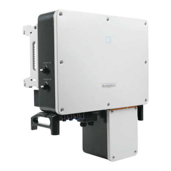
2 Product Introduction User Manual 2.2.2 Appearance *The image shown here is for reference only. The actual product you receive may differ. D D e e s s c c r r i i p p t t i i o o n n N N o o . -
Page 17: Dimensions
User Manual 2 Product Introduction 2.2.3 Dimensions F F i i g g u u r r e e 2 2 - - 2 2 Dimensions of the Inverter *The image shown here is for reference only. The actual product you receive may differ. D D i i m m e e n n s s i i o o n n s s T T y y p p e e D D i i m m e e n n s s i i o o n n s s ( ( W W 1 1 * * H H 1 1 * * D D 1 1 ) ) -
Page 18: Dc Switch
2.2.5 DC Switch The DC switch is used to disconnect the DC current safely whenever necessary. The SG36CX-US and SG60CX-US are equipped with two DC switches separately controlling a group of DC inputs. The correspondence is as follows: Turn the DC switches to the ON position before restarting the inverter. -
Page 19: Circuit Diagram
User Manual 2 Product Introduction 2.3 Circuit Diagram The MPPT is utilized for DC input to ensure the maximum power from the PV array at different PV input conditions. The inversion circuit converts the DC power into AC power and feeds the AC power into the utility grid through the AC terminal. The protection circuit is equipped to ensure the safe operation of the device and personal safety. - Page 20 2 Product Introduction User Manual Before enabling the PID recovery function, make sure the voltage polarity • of the PV modules to ground meets requirement. If there are any questions, contact the PV module manufacturer or read its corresponding user manual.
-
Page 21: Unpacking And Storage
Check the delivery scope for completeness according to the packing list. • Contact SUNGROW or the supplier in case there is any damage or incompleteness. Do not dispose of the original packing case. It is recommended to store the inverter in it. -
Page 22: Scope Of Delivery
The mounting-bracket includes 2 mounting-bracket components and 1 connecting bar. b. The SG36CX-US, SG60CX-US are respectively provided with 8, 12 pairs of DC connectors and cord end terminals. c. The screws include 6 M4×10 screws, 2 M6×65 screws, and 2 M12 hex socket... -
Page 23: Inverter Storage
User Manual 3 Unpacking and Storage d. The documents include the quick installation guide, packing list, warranty card, etc. 3.4 Inverter Storage Proper storage is required if the inverter is not installed immediately. Store the inverter in the original packing case with the desiccant inside. •... -
Page 24: Mechanical Mounting
Mechanical Mounting 4.1 Safety During Mounting Ensure there is no electrical connection before installation. In order to avoid electric shock or other injury, be sure there is no electricity or conduit installations before drilling holes. Risk of injury due to improper handling Always follow the instructions when moving and positioning the inverter. -
Page 25: Carrier Requirements
User Manual 4 Mechanical Mounting The ambient temperature and relative humidity must meet the following • requirements. Do not install the inverter outdoors in areas with salt damage, which mainly refer to • the areas within 500 m away from the coast. The deposition of salt fog varies largely with nearby seawater characteristics, sea wind, precipitation, relative humidity, terrain, and forest coverage. -
Page 26: Installation Clearance Requirements
Contact SUNGORW if you have any question. About X-RACK ordering issues, please contact you local SUNGROW Sales or SUNGROW authorized distributors. 4.2.4 Installation Clearance Requirements Reserve enough clearance around the inverter to ensure sufficient space for heat •... - Page 27 User Manual 4 Mechanical Mounting * The distance can be shortened to 200mm according to onsite conditions. In case the distance is less than 450mm, remove the inverter from the mounting-bracket or wall before maintaining fans. The distance between the bottom of the inverter and the ground surface is determined according to the bending radius of the AC cable used and the installation environment.
- Page 28 4 Mechanical Mounting User Manual In case of multiple inverters, reserve specific clearance between the inverters, as • shown below. In case of back-to-back installation, reserve specific clearance of at least 500m • between the two inverters, as is shown below. Install the inverter at an appropriate height for ease of viewing LED indicators and •...
-
Page 29: Installation Tools
User Manual 4 Mechanical Mounting 4.3 Installation Tools Installation tools include but are not limited to the following recommended ones. If necessary, use other auxiliary tools on site. Table 4-1 Tool Specification S S p p e e c c i i f f i i c c a a t t i i o o n n N N o o . -
Page 30: Moving The Inverter
4 Mechanical Mounting User Manual S S p p e e c c i i f f i i c c a a t t i i o o n n N N o o . . Opening:13mm, 16mm Crimp range 4~6mm Range≥1100Vdc 15mm 4.4 Moving the Inverter... -
Page 31: Hoisting Transport
User Manual 4 Mechanical Mounting 4.4.2 Hoisting Transport Step 1 Release the sealing screws on the mounting ears and store them properly. Anchor two M12 thread lifting rings to the hangers of the inverter. Step 2 Lead the sling through the two lifting rings and fasten the tie-down strap. Step 3 Hoist the inverter, and stop to check for safety when the inverter is 100mm above the ground. -
Page 32: Dimensions Of Mounting-Bracket
F F i i g g u u r r e e 4 4 - - 1 1 Dimensions of mounting-bracket T T y y p p e e L L 1 1 L L 2 2 H H 1 1 H H 2 2 687mm/ 640mm/ 564mm/ SG36CX-US 235mm/9.3” 26.7” 25.2” 22.2” 767mm/ 720mm/ 614.5mm/ 285mm/ SG60CX-US 30.2”... -
Page 33: Mounting Steps
User Manual 4 Mechanical Mounting S S p p e e c c i i f f i i c c a a t t i i o o n n I I t t e e m m Level Drill bit: φ12 Hammer drill Including 16mm socket... - Page 34 4 Mechanical Mounting User Manual Table 4-2 Fastening sequence C C o o m m p p o o n n e e n n t t s s D D e e s s c c r r i i p p t t i i o o n n N N o o .
-
Page 35: Wall-Mounted Installation
User Manual 4 Mechanical Mounting - - - - E E n n d d 4.7 Wall-Mounted Installation 4.7.1 Preparation Before Mounting T T o o o o l l s s S S p p e e c c i i f f i i c c a a t t i i o o n n I I t t e e m m Phillips screwdriver/ electric M4, M6... - Page 36 4 Mechanical Mounting User Manual Step 2 Level the assembled mounting-bracket by using the level, and mark the positions for drilling holes on the installation site. Step 3 Insert the expansion bolts into the holes and secure them with a rubber hammer. Fasten the nut with a wrench to expand the bolt.
- Page 37 User Manual 4 Mechanical Mounting Table 4-3 Fastening sequence D D e e s s i i g g n n a a t t i i o o n n D D e e s s c c r r i i p p t t i i o o n n I I t t e e m m Wall Fastening the bolt in the sequence of nut, spring washer,...
- Page 38 4 Mechanical Mounting User Manual - - - - E E n n d d...
-
Page 39: Electrical Connection
Electrical Connection 5.1 Safety Instructions Prior to any electrical connections, keep in mind that the inverter has dual power supplies. It is mandatory for the qualified personnel to wear personal protective equipments (PPE) during the electrical work. Danger to life due to high voltage inside the inverter! The PV string will generate lethal high voltage when exposed to sunlight. -
Page 40: Electrical Connection Overview
T T e e r r m m i i n n a a l l M M a a r r k k N N o o t t e e MC4 PV connector SG36CX-US: 8 pairs of terminals PV terminals + / - SG60CX-US: 12 pairs of terminals... - Page 41 Outdoor single- The same as that of the PE Groundin- core copper wire wire in the AC cable g cable cable L1,L2,L3,N wire (SG36CX-US): 6~2/0AWG Outdoor multi- L1,L2,L3,N wire 3–4 AC cable core copper or (SG60CX-US): 5~2/0AWG aluminium cable PE wire: refer to "Table 5-2...
-
Page 42: Additional Grounding Connection
R R e e c c o o m m m m e e n n d d e e d d P P E E w w i i r r e e c c r r o o s s s s s s e e c c t t i i o o n n r r a a n n g g e e I I t t e e m m SG36CX-US/ 6AWG-4AWG SG60CX-US 5.4 Additional Grounding Connection... - Page 43 User Manual 5 Electrical Connection 1:Heat shrink tubing 2:OT/DT terminal Step 2 Remove the screw on the grounding terminal and fasten the cable with a screwdriver. Step 3 Apply paint to the grounding terminal to ensure corrosion resistance. - - - - E E n n d d The grounding screws have been anchored to the side of the inverter before delivery, and do not need to be prepared.
-
Page 44: Ac Cable Connection
M M u u l l t t i i p p l l e e I I n n v v e e r r t t e e r r s s i i n n p p a a r r a a l l l l e e l l C C o o n n n n e e c c t t i i o o n n If multiple inverters are connected in parallel to the grid, ensure that the total number of parallel inverters does not exceed 30. Otherwise, please contact SUNGROW for technical approval. -
Page 45: Requirements For Ot/Dt Terminal
User Manual 5 Electrical Connection The transformer must be protected against overloading and short circuit. • The transformer is an important part of a grid-connected PV generation system. The • faults tolerance capacity of the transformer should be taken into account at all times. The faults include: system short circuit, grounding fault, voltage drop, etc. -
Page 46: Connection Procedure
5 Electrical Connection User Manual 5.5.4 Connection Procedure Step 1 Disconnect the AC-side circuit breaker and prevent it from inadvertent reconnection by implementing a lok-out, tag-out(LOTO), in accordance with local regulations. Step 2 Use an torx wrench to remove the four screws on the AC junction box. Step 3 Use a Phillips screwdriver to remove the two screws on the transparent protective cover. - Page 47 User Manual 5 Electrical Connection Step 7 Secure the cable to corresponding terminals. Observe the terminal layout on the block. Do not connect the phase wires to "PE" terminal or PE wire to "N" terminal. Otherwise, unrecoverable damage to the inverter will occur.
-
Page 48: Dc Cable Connection
5 Electrical Connection User Manual Ensure that the depth L of the socket used is not less than 18mm. Step 8 Secure the transparent protective cover, and secure it with Phillips screwdriver. Step 9 Secure the cover of the AC junction box, and secure it with torx wrench. - - - - E E n n d d 5.6 DC Cable Connection Electric shock! -
Page 49: Pv Input Configuration
O O p p e e n n c c i i r r c c u u i i t t v v o o l l t t a a g g e e l l i i m m i i t t SG36CX-US... -
Page 50: Connection Procedure
5 Electrical Connection User Manual 5.6.2 Connection Procedure SUNGROW provides corresponding plug connectors in the scope of delivery for quick connection of PV inputs. DC cables should be connected to the inverter via PV connectors which are included in the scope of delivery. -
Page 51: Installing The Pv Connectors
User Manual 5 Electrical Connection Step 4 Check for correct polarity. The inverter will not function properly if any PV polarity is reversed. - - - - E E n n d d 5.6.3 Installing the PV Connectors Step 1 Rotate all the DC switches to "OFF" position. Skip performing step1 when the actual device is not equipped with DC switches. -
Page 52: Communication Junction Box
Arc or contactor over temperature may occur if the PV connectors are not firmly in place, and SUNGROW shall not be held liable for any damage caused. Step 4 Follow the foregoing steps to connect PV connectors of other PV strings. -
Page 53: Communication Wiring Board
User Manual 5 Electrical Connection - - - - E E n n d d 5.8 Communication Wiring Board The communication board of the inverter includes two layers. The upper layer communication board mainly includes RS485 communication interfaces while the lower layer communication board mainly includes DI/DO interface and DRM interface. -
Page 54: Rs485 Communication System
5 Electrical Connection User Manual A 120Ω resistor can be connected in parallel between RS485-1 A/B pins by configuring the dip switch. RS485-1 crimp interface and RJ45 interface serve as the same function with different wiring manner. 5.9.2 RS485 Communication System Either Sunspec or SG Modbus is available, but the two communication protocols cannot be adopted at the same time. - Page 55 User Manual 5 Electrical Connection When more than 15 inverters are connected on the same daisy chain, the inverters on two ends of the chain should be equipped with terminal resistors of 120Ω to ensure communication quality by configuring the dip switch (SW1), and the shielding layer of the communication cable should be single-point grounded.
-
Page 56: Connection Procedure(Crimp)
5 Electrical Connection User Manual 5.9.3 Connection Procedure(Crimp) RS485 communication cables should be shielded twisted pair cables or shielded twisted pair Ethernet cables. There are three communication terminals, and the silkscreen marks are COM1/COM2/COM3. Please choose according to the actual situation. Step 1 Remove the communication junction box, see "5.7.1 Remove the Junction Box". -
Page 57: Connection Procedure (Rj45 Ethernet Port)
User Manual 5 Electrical Connection Step 5 Insert the terminal base into the corresponding terminal. Table 5-3 Terminal definition N N o o D D e e f f i i n n i i t t i i o o n n RS485 A+ RS485 A+ RS485 B-... - Page 58 5 Electrical Connection User Manual O O u u t t e e r r d d i i a a m m e e t t e e r r D D ( ( m m m m ) ) S S e e a a l l 4.5~6 6~12...
-
Page 59: Dry Contact Connection
User Manual 5 Electrical Connection 5.10 Dry Contact Connection Dry contact cables require a cross section of 18AWG~16AWG. The connection procedure of the dry contact is the same as that of the RS485 terminal block. 5.10.1 Dry Contact Function The configuration circuit board is provided with fault output dry contact and emergency shutdown dry contact, as shown in the Figure below. - Page 60 5 Electrical Connection User Manual F F i i g g u u r r e e 5 5 - - 5 5 Normal open contact F F i i g g u u r r e e 5 5 - - 6 6 Normal close contact Devices connected to the relay should comply with related requirements: A A C C - - S S i i d d e e R R e e q q u u i i r r e e m m e e n n t t s s D D C C - - S S i i d d e e R R e e q q u u i i r r e e m m e e n n t t s s...
-
Page 61: Wiring Procedure
5.9.3 Connection Procedure 5.11 Communication Module Connection (optional) Connect the communication module produced by SUNGROW, such as WiNet, Eye, or E-Net to the communication accessory port. After successful connection, information such as power generation and running state of the inverter can be viewed via the App on the phone. -
Page 62: Module-Level Rapid Shutdown Device Connection (Optional)
Smart PV Panels integrated with RSDs according to NEC 690.12 & CA22.2 NO. 330 regulations. When the SUNGROW inverter is connected to the AC grid, the PLC transmitter receives power via an integrated power supply. Then, Once the PLC transmitter is powered, it will send a ‘keep alive’ signal to RSDs in •... -
Page 63: Module-Level Rapid Shutdown Device Connection
SUNGROW inverter directly to RSDs. SUNGROW PLC transmitter supports most of the popular RSDs or Smart PV panel brands and models. Confirm with SUNGROW to check the detailed list of RSD brands and models supported before beginning the PV system design. -
Page 64: Commissioning
After the RSDs or Smart PV panels are installed, please adhere the Rapid Shutdown Warning Label from the RSD or Smart PV panel package to: A visible place on SUNGROW Inverter AC switch box / PV System Disconnect panel/ •... - Page 65 User Manual 6 Commissioning A visible place on PV System Disconnect panel/ Service Entrance panel etc. when • there are multiple inverters in the PV system.
-
Page 66: Isolarcloud App
This manual describes only how to achieve near-end maintenance via the Bluetooth connection. For maintenance through SUNGROW communication device, refer to the related manuals in SUNGROW website Screenshots in this manual are based on the Android system V2.1.6, and the actual interfaces may differ. -
Page 67: Login
User Manual 7 iSolarCloud App 7.3 Login 7.3.1 Requirements The following items should meet requirements: The AC or DC side of the inverter is powered-on. • The smart phone is within 5m of the inverter and there are no obstructions in •... - Page 68 To set inverter parameters related to grid protection and grid support, contact SUNGROW to obtain the advanced account and corresponding password. Step 4 If the inverter is not initialized, you will enter the quick setting screen to initialize protection parameters.
-
Page 69: Function Overview
User Manual 7 iSolarCloud App F F i i g g u u r r e e 7 7 - - 3 3 Initialization protection parameter Reset the grid protection parameters if the country setting is incorrect. Otherwise, faults will occur. In the US region, conformity to UL 1741 includes compliance with applicable requirements of IEEE 1547, IEEE 1547.1, California Electric Rule 21, Hawaiian Electric Co. -
Page 70: Home Page
7 iSolarCloud App User Manual F F i i g g u u r r e e 7 7 - - 4 4 App function tree map 7.5 Home page After login, the home page is as follows: F F i i g g u u r r e e 7 7 - - 5 5 Home page Table 7-1 Home page description D D e e s s i i g g n n a a t t i i o o n n D D e e s s c c r r i i p p t t i i o o n n... - Page 71 User Manual 7 iSolarCloud App D D e e s s i i g g n n a a t t i i o o n n D D e e s s c c r r i i p p t t i i o o n n N N o o .
-
Page 72: Running Information
7 iSolarCloud App User Manual Table 7-3 Description of PID function state D D e e s s c c r r i i p p t t i i o o n n S S t t a a t t e e PID recovery The inverters perform PID recovery actively. - Page 73 User Manual 7 iSolarCloud App Table 7-4 Run information C C l l a a s s s s i i f f i i c c a a - - D D e e s s c c r r i i p p t t i i o o n n P P a a r r a a m m e e t t e e r r t t i i o o n n String n Voltage...
-
Page 74: History Record
7 iSolarCloud App User Manual C C l l a a s s s s i i f f i i c c a a - - D D e e s s c c r r i i p p t t i i o o n n P P a a r r a a m m e e t t e e r r t t i i o o n n Phase B Current... -
Page 75: Yields Records
User Manual 7 iSolarCloud App F F i i g g u u r r e e 7 7 - - 9 9 Detailed fault and alarm information 7.7.2 Yields Records User can view various energy records: power curve, daily energy histogram, monthly energy histogram, and annual energy histogram. -
Page 76: Event Records
7 iSolarCloud App User Manual F F i i g g u u r r e e 7 7 - - 1 1 0 0 Power Curve Tap the time bar on the top of the screen to select a time segment and view the corresponding power curve. -
Page 77: Parameter Setting
User Manual 7 iSolarCloud App F F i i g g u u r r e e 7 7 - - 1 1 1 1 More 7.8.1 Parameter Setting Tap " " to enter the setting screen, as shown in the following Figure. F F i i g g u u r r e e 7 7 - - 1 1 2 2 Settings System Parameters •... - Page 78 7 iSolarCloud App User Manual Tap" " to enter Operation Parameters screen, as shown in the following Figure. F F i i g g u u r r e e 7 7 - - 1 1 4 4 Operation Parameters Running Time •...
- Page 79 User Manual 7 iSolarCloud App Tap" " to enter AFCI Parameters screen, on which AFD self-test function and AFCI activation function can be enabled or disabled; and AFD alarm can be cleared, as shown in the following Figure. F F i i g g u u r r e e 7 7 - - 1 1 7 7 AFD Parameters Power Regulation Parameters •...
- Page 80 7 iSolarCloud App User Manual D D e e f f i i n n i i t t i i o o n n / / S S e e t t t t i i n n g g R R a a n n g g e e P P a a r r a a m m e e t t e e r r d d e e s s c c r r i i p p t t i i o o n n...
- Page 81 User Manual 7 iSolarCloud App D D e e f f i i n n i i t t i i o o n n / / S S e e t t t t i i n n g g R R a a n n g g e e P P a a r r a a m m e e t t e e r r d d e e s s c c r r i i p p t t i i o o n n...
- Page 82 7 iSolarCloud App User Manual D D e e f f i i n n i i t t i i o o n n / / S S e e t t t t i i n n g g R R a a n n g g e e P P a a r r a a m m e e t t e e r r d d e e s s c c r r i i p p t t i i o o n n...
- Page 83 User Manual 7 iSolarCloud App F F i i g g u u r r e e 7 7 - - 1 1 9 9 Q(U) Curve F F i i g g u u r r e e 7 7 - - 2 2 0 0 Q(P) Curve Communication Parameters •...
-
Page 84: Firmware Update
P P r r e e p p a a r r a a t t i i o o n n o o f f f f i i r r m m w w a a r r e e u u p p d d a a t t e e p p a a c c k k a a g g e e Contact the supplier or Sungrow to get the update package (. zip file) and store the package in the specified path. - Page 85 User Manual 7 iSolarCloud App F F i i g g u u r r e e 7 7 - - 2 2 3 3 Change password The password shall consisit of 8–20 digits, including letters and numbers.
-
Page 86: System Decommissioning
System Decommissioning 8.1 Disconnecting the Inverter For maintenance or other service work, the inverter must be switched off. Proceed as follows to disconnect the inverter from the AC and DC power sources. Lethal voltages or damage to the inverter will follow if otherwise. Step 1 Disconnect the external AC circuit breaker and secure it against reconnection. -
Page 87: Disposal Of The Inverter
User Manual 8 System Decommissioning Step 1 Refer to "5 Electrical Connection"for the inverter disconnection of all cables in reverse steps. Step 2 Dismantle the inverter referring to "4 Mechanical Mounting"in reverse steps. Step 3 If necessary, remove the wall-mounting bracket from the wall. Step 4 If the inverter will be reinstalled in the future, please refer to "3.4 Inverter Storage"for a... -
Page 88: Troubleshooting And Maintenance
App or the LCD. 3. Check whether the cross-sectional area of the AC cable meets the requirement. 4. If the fault is not caused by the foregoing reasons and still exists, contact SUNGROW. Grid transient Generally, the inverter will be reconnected overvoltage, to the grid after the grid returns to normal. - Page 89 3. Check whether the AC cable is firmly in place. 4. If the fault is not caused by the foregoing reasons and still exists, contact SUNGROW. Generally, the inverter will be reconnected to the grid after the grid returns to normal. If the fault occurs repeatedly: 1.
- Page 90 SUNGROW. Wait for the inverter to return to normal. Disconnect the AC and DC switches, and Device anomaly reconnect the AC and DC switches 15 minutes later to restart the inverter. If the fault still exists, contact SUNGROW.
- Page 91 AC and DC cables are well insulated. 3. If the fault is not caused by the foregoing reasons and still exists, contact SUNGROW. Generally, the inverter will be reconnected to the grid after the grid returns to normal. If...
- Page 92 Wait for the inverter to return to normal. power is excessively large and out of the If the fault still exists, contact SUNGROW. normal operation range of the inverter. Generally, the inverter will be reconnected to the grid after the grid returns to normal. If the fault occurs repeatedly: 1.
- Page 93 Device anomaly reconnect the AC and DC switches 15 minutes later to restart the inverter. If the fault still exists, contact SUNGROW. Wait for the inverter to return to normal. If the fault occurs repeatedly: 1. Check whether the ISO resistance...
- Page 94 Disconnect the AC and DC switches, and Device anomaly reconnect the AC and DC switches 15 040-042 minutes later to restart the inverter. If the fault still exists, contact SUNGROW. Low ambient temperature, the Shutdown and disconnect the inverter. ambient temperature is...
- Page 95 3. If the fault is not caused by the foregoing reasons and still exists, contact SUNGROW. Restart the inverter or clear the fault through Protection self-check the App. failure on grid side If the fault still exists, contact SUNGROW.
- Page 96 Device anomaly reconnect the AC and DC switches 15 116-117 minutes later to restart the inverter. If the fault still exists, contact SUNGROW. 1. Check if the xth PV string needs to be connected. If not, ignore the alarm; and If so, check the connection status and make sure it is connected reliably.
- Page 97 String x reverse 532-547 2. If the fault is not caused by the foregoing connection alarm reasons and still exists, contact SUNGROW. *The code 532 to code 547 are corresponding to string 1 to string 16 respectively. 1. Check whether the corresponding module is sheltered.
-
Page 98: Maintenance
Restart the inverter only after removing the fault that impairs safety performance. As the inverter contains no component parts that can be maintained, never arbitrarily replace any internal components. For any maintenance requirement, please contact SUNGROW. Otherwise, SUNGROW shall not be held liable for any damage caused. -
Page 99: Routine Maintenance
User Manual 9 Troubleshooting and Maintenance 9.2.1 Routine Maintenance I I t t e e m m M M e e t t h h o o d d P P e e r r i i o o d d Check the temperature and dust of the inverter. - Page 100 9 Troubleshooting and Maintenance User Manual F F a a n n M M a a i i n n t t e e n n a a n n c c e e Stop the inverter and disconnect it from all power supplies before •...
- Page 101 User Manual 9 Troubleshooting and Maintenance Step 5 Reinstall the fan back to the inverter in reverse order and restart the inverter. - - - - E E n n d d...
-
Page 102: Appendix
10 Appendix 10.1 Technical Data P P a a r r a a m m e e t t e e r r s s S S G G 3 3 6 6 C C X X - - U U S S S S G G 6 6 0 0 C C X X - - U U S S I I n n p p u u t t ( ( D D C C ) ) Max. - Page 103 User Manual 10 Appendix P P a a r r a a m m e e t t e e r r s s S S G G 3 3 6 6 C C X X - - U U S S S S G G 6 6 0 0 C C X X - - U U S S 98.60% 98.80%...
- Page 104 10 Appendix User Manual P P a a r r a a m m e e t t e e r r s s S S G G 3 3 6 6 C C X X - - U U S S S S G G 6 6 0 0 C C X X - - U U S S OT (#6 - 2/0AWG, OT (#5 - 2/0AWG, Cu or...
- Page 105 E E x x c c l l u u s s i i o o n n o o f f L L i i a a b b i i l l i i t t y y In the following circumstances, SUNGROW has the right to refuse to honor the quality...
- Page 106 The fault or damage is caused by installation, repairs, modification, or disassembly • performed by a service provider or personnel not from SUNGROW. The fault or damage is caused by the use of non-standard or non-SUNGROW • components or software.
- Page 107 M M a a l l a a y y s s i i a a P P h h i i l l i i p p p p i i n n e e s s Sungrow SEA Sungrow Power Supply Co., Ltd Selangor Darul Ehsan Mandaluyong City...
- Page 108 L L u u x x e e m m b b o o u u r r g g ( ( B B e e n n e e l l u u s s ) ) Sungrow Vietnam...
- Page 109 Sungrow Power Supply Co., Ltd. Add: No.1699 Xiyou Rd.,New & High Technology Industrial Development Zone, 230088,Hefei, P. R. China. Web: www.sungrowpower.com E-mail: info@sungrow.cn Tel: +86 551 6532 7834 / 6532 7845 Specifications are subject to changes without advance notice.
Need help?
Do you have a question about the SG36CX-US and is the answer not in the manual?
Questions and answers