Sungrow SG60KTL User Manual
Pv grid-connected inverter
Hide thumbs
Also See for SG60KTL:
- Quick installation quide (15 pages) ,
- Installation manual (6 pages) ,
- User manual (106 pages)

Related Manuals for Sungrow SG60KTL


Summary of Contents for Sungrow SG60KTL
- Page 1 User Manual SG60KTL PV Grid-connected Inverter SG60KTL-V142-UEN-Ver11-201712 Version: 1.1...
- Page 3 About This Manual This manual is for string inverter SG60KTL (hereinafter referred to as inverter unless otherwise specified). The inverter is grid-connected, transformer-less, robust and of high conversion efficiency. We hope the inverter will satisfy you when you use it with your PV plant system.
- Page 4 Symbols Explanation Important instructions contained in this manual should be followed during installation, operation and maintenance of the inverter. And they will be highlighted by the following symbols. DANGER indicates a hazard with a high level of risk which, if not avoided, will result in death or serious injury.
- Page 5 Symbols on the Inverter Body...
-
Page 6: Table Of Contents
Content About This Manual ................I 1 Safety Instructions ..............1 2 Product Description ..............6 Intended Usage ...................... 6 Product Introduction .................... 7 2.2.1 Appearance ......................... 7 2.2.2 Dimensions ........................8 2.2.3 LCD Display ........................8 ... - Page 7 Maintenance ......................56 9.2.1 Routine Maintenance ................... 56 9.2.2 Maintenance Instruction ..................57 Contact Sungrow Service ................. 58 10 Operation of LCD Display ............60 10.1 Description of Button Function ..............60 ...
- Page 8 10.5 Checking Running Information ..............63 10.6 Checking History Information ................ 65 10.6.1 Checking Running Records ................65 10.6.2 Checking Fault Records ..................65 10.6.3 Checking History Event Records ..............66 10.6.4 Checking Energy Records ................. 66 ...
- Page 9 10.13.1 10min Max-V ....................... 84 10.13.2 Grid Unbalance ....................85 11 Appendix ................86 11.1 Technical Data ...................... 86 11.2 Exclusion of Liability ..................87 11.3 About Us ........................ 88 11.4 Contact Information ..................
-
Page 11: 1 Safety Instructions
1 Safety Instructions The inverter has been designed and tested strictly according to the international safety regulations. As electrical and electronic equipment, safety instructions related to them must be complied with during installation, commissioning, operation and maintenance. Incorrect operation or work may result in damage to: ... - Page 12 If there is visible damage to the packaging or the inner contents, or if there is something missing, contact Sungrow or the forwarding company. During Installation Make sure inverter is not electrically connected before installing the inverter.
- Page 13 Operate the inverter by strictly following the descriptions in this manual to avoid unnecessary injury to the persons and damage to the device. Arc flash, fire or explosion may follow if otherwise and Sungrow will hold no liability for the damages followed.
- Page 14 Inverter contains no owner serviceable part inside. Please contact local authorized personnel if any service work is required. Do not replace the inverter internal components without permission. Damages may follow and it may void any or all warranty rights from Sungrow.
- Page 15 User Manual 1 Safety Instructions There is a risk of inverter damage due to electrostatic discharge! The printed circuit boards contain components sensitive to electrostatic discharge. Wear a grounding wrist band when handling the boards. Avoid unnecessary touch with the boards. Others All safety instructions, warning labels nameplate on the inverter: ...
-
Page 16: 2 Product Description
2 Product Description 2.1 Intended Usage SG60KTL inverter, 3-phase string inverter without transformer, is a crucial unit in the PV power system. Inverter is designed to convert the direct current power generated from the PV modules into grid-compatible AC current and feeds the AC current to the utility grid. -
Page 17: Product Introduction
User Manual 2 Product Description Customer can choose to connect the neutral cable or not, it’s not mandatory to connect the neutral cable to the inverter. More than one inverter can be connected to the system if the capacity of the PV system exceeds the capacity of a single inverter. -
Page 18: Dimensions
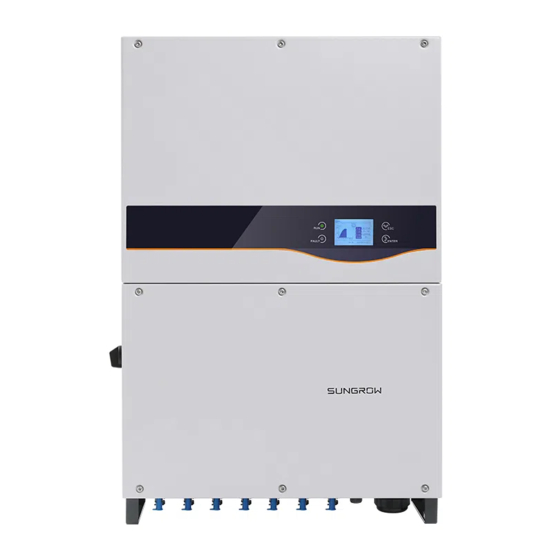
2 Product Description User Manual * Pictures are indicative only. Product in kind prevail. Name Description Human-computer interface for viewing of the running LCD display information and parameter configuration. Electrical Include DC terminal, AC terminal ad RS485 connection area communication terminal. Handles are designed for transporting, installing and Handles disassembling the inverter... -
Page 19: Dc Switch
User Manual 2 Product Description Fig. 2-4 LCD display Tab. 2-1 Description of LCD display Name Description “RUN” and FAULT”. Indicate the inverter operation state. indicators Detailed explanation is shown in Tab. 2-2 Two buttons for LCD operation and parameter configuration. Buttons Detailed explanation is shown in 0 Display inverter present state, operation information, history... -
Page 20: Technical Description
DC switch is used to disconnect the DC current safely; inverter provides standard RS485 ports for communication. User can check running data and set related parameter through the LCD display. Fig. 2-5 Circuit diagram of SG60KTL 2.3.2 Function Description ... -
Page 21: Derating
User Manual 2 Product Description Data storage and display Inverter achieves the running information, fault records and etc. and displays them on the integrated LCD display. Parameter Configuration Inverter provides various parameter configuration for inverter optimal operation. Communication Interface Standard RS485 port, can be connected to monitoring device and PV system ... - Page 22 2 Product Description User Manual Over-temperature Derating High ambient temperature, fan broken or poor ventilation will lead to inverter power derating. When the module temperature exceeds the upper limit, inverter will derate power output until the temperature drops within the permissible range. ...
- Page 23 User Manual 2 Product Description = Pn × (Vgrid /230V) [Vmin…266V] Fig. 2-6 Grid under-voltage derating...
-
Page 24: 3 Installation Flow
3 Installation Flow Fig. 3-1 shows the installation flow of the inverter and Tab. 3-1 gives the detailed explanation. Fig. 3-1 Installation flow... - Page 25 User Manual 3 Installation Flow Tab. 3-1 Description of installation flow Step Description Reference Unpacking and inspection Read the User Manual, especially the section on “Safety Instruction” Store the inverter if it is not to be installed immediately Select optimal installation site Move the inverter to the installation site Install the inverter to the selected installation site Electrical connection;...
-
Page 26: 4 Unpacking And Storage
Check the completeness of delivery contents according to the packing list. Check the inner contents for damage after unpacking. If any damage is found, please contact Sungrow or the forwarding company. Do not disposal of the original packaging. It is best to store the inverter in its original packaging. - Page 27 Fig. 4-2 Inverter nameplate *Image shown here is indicative only. Product in kind prevail. Item Description SUNGROW logo and product type Inverter technical data Marks of certification institutions Company name, website and origin Tab. 4-1 Description of icons on the nameplate...
-
Page 28: Scope Of Delivery
Store the inverter properly when the inverter is not to be installed immediately. Sungrow shall hold no liability for the corrosion of the device or the failure of device internal components caused by storage of the device not following the requirements specified in this manual. - Page 29 Replace the packing in time if necessary. The packing should be upright. If the inverter is stored for half a year or longer time, local installer or service dept. of Sungrow should perform a comprehensive test before connecting the inverter into PV power system.
-
Page 30: 5 Mechanical Installation
5 Mechanical Installation 5.1 Installation Site Selection Select an optimal installation site for install safe operation, long service life and outstanding performance. Take the load capacity of the wall into account. The wall (concrete wall or metal frame) should be strong enough for the weight of the inverter over a long period. ... - Page 31 User Manual 5 Mechanical Installation Install the inverter at eye-level for easy button operation and display read. Do not install the inverter upside down or with an inclination. With an IP65 protection rating, the inverter can be installed both outdoors and indoors. ...
-
Page 32: Moving Inverter To Installation Site
5 Mechanical Installation User Manual Take enough space for convection into consideration when installing multiple inverters. It is suggest to stagers the inverters. Do not install the inverter in a confined space. Inverter will not work normally if otherwise. ... -
Page 33: Installing The Inverter
User Manual 5 Mechanical Installation Move the inverter by two persons or proper moving devices. Do not release the equipment unless it has been secured to the wall firmly. 5.3 Installing the Inverter Inverter is installed to the wall by the backplate enclosed in the packing. If you do not use the supplied backplate, you can drill holes as per specifications below: 2-M4X7 3-26X11... -
Page 34: Installing To Metal Frame
5 Mechanical Installation User Manual 5.3.1 Installing to Metal Frame Remove the backplate and fasteners from the packaging. Step 1 Place the backplate to the chosen metal frame and adjust it to proper position and Step 2 height. Mark the position for holes drilling according to the holes position of the backplate. Step 3 Drill holes according to the marks make before. -
Page 35: Installing To Concrete Wall
User Manual 5 Mechanical Installation 5.3.2 Installing to Concrete Wall Remove the backplate and corresponding fasteners from the packaging. Step 1 Place the backplate to the chosen concrete wall and adjust it to proper position and Step 2 height. Mark the position for holes drilling according to the holes position of the backplate. Step 3 Drill holes according to the marks make before. - Page 36 5 Mechanical Installation User Manual Secure the backplate to the wall firmly by the supplied expansion bolt sets. Torque of Step 5 the fasten nut is 35 Nm. Install the inverter cap. Step 6 Lift the inverter above the backplate and then slide down to make sure they match Step 7 perfectly.
-
Page 37: 6 Electrical Connection
6 Electrical Connection Once the inverter is secured to the installation site, it can be connected to the PV system. All electrical connection must comply with local regulations and related electrical rules (AS 4777.1 etc.). Improper cable connection may lead to fetal personal injury or device permanent damages. -
Page 38: Ac Side Cable Connection
For detailed parameter, please refer to 11.1 Technical Data. AC Circuit Breaker An independent three or four-pole circuit breaker is installed outside the output side of the inverter to ensure that the inverter can be disconnected safely. Inverter Recommended AC circuit breaker SG60KTL 120A... - Page 39 Several inverters are in parallel connection to the low voltage side of the MV transformer. The high voltage side is connected to the middle voltage grid. Requirements: If the number of the grid-connected inverters exceed 40, please contact Sungrow. Nominal power of the transformer low voltage side matches the inverter output power.
- Page 40 The inverter apparent power is not permitted to exceed the transformer power. The maximum nominal AC current of all connected inverters must be taken into account. If the number of the grid-connected inverters exceed 40, please contact Sungrow. The transformer must be protected from overloading and short circuiting.
-
Page 41: Grid Connection
User Manual 6 Electrical Connection The country-specific power grid frequency should be taken into account at all times. The country-specific standards and directives should be taken into account at all times. 6.2.2 Grid Connection AC terminal block is on the bottom of the inverter. AC connection is the 3-phase-5-wire grid connection (L1, L2, L3, N and PE). - Page 42 6 Electrical Connection User Manual Disconnect the AC circuit breaker and ensure it will not reconnect accidentally. Step 1 Unscrew the 6 bolts on the front cover of the lower Step 2 junction box. Peal the cables as shown below. Step 3 The AC cables must be Hard-line.
- Page 43 User Manual 6 Electrical Connection Cross-section of the AC cable (mm Max. length of the AC cables (m) 0-50 50-100 >100 Select the adaptive wire diameter of AC cable gland according to actual AC cable Step 4 diameter. Remove or install the two AC cable glands on the bottom of the device by torque of recommended value.
- Page 44 6 Electrical Connection User Manual * Pictures here are indicatively only. Product in kind prevail. If the cross-section of the AC cable is sectorial, please place the apex(A) of sector upside and then fix the AC cable to the corresponding terminals.. ...
-
Page 45: Pv Array Connection
User Manual 6 Electrical Connection 6.3 PV Array Connection Lethal voltage exists! PV arrays produce electrical energy when exposed to light and thus can create an electrical shock hazard. Make sure that the PV impedance to the ground is proper before connecting the PV array to the inverter. - Page 46 6 Electrical Connection User Manual Before connecting PV array to inverter, the following electrical parameters must be met. Total DC power Max. open-circuit voltage Short-circuit current limit limit limit for each input 67500W 1000V 140A Considering the negative voltage temperature coefficient of PV cells, more attention should be paid to the open-circuit voltage of PV strings when the ambient temperature is the lowest.
-
Page 47: Pv Input Connection
User Manual 6 Electrical Connection 6.3.2 PV Input Connection DC Cable Requirements The cross-section of the DC cable must be selected carefully in order to prevent accidentally disconnections of the inverter from the grid due to high impedance of the cable. Tab. -
Page 48: Grounding The Inverter
6 Electrical Connection User Manual 6.4 Grounding the Inverter Due to the transformer-less design of the inverter, neither the DC positive pole nor the DC negative pole of the PV string can be grounded. 6.4.1 Grounding System Overview In this PV system, all non-current carrying metal parts and device enclosure should be grounded (such as the PV array frame and inverter enclosure). -
Page 49: Communication Connection
The ground connection of this second PE terminal cannot replace the connection of the PE terminal of the AC cables. Make sure the two PE terminals are all grounded reliably. Sungrow shall hold no liability for any possible consequences caused by ignorance of this warning. -
Page 50: Rs485 Communication System
Shielded twisted pair cables or Shielded twisted pair Ethernet cable. A converter such as RS485-232 converter or SolarInfo Logger is needed to convert signal between inverter and PC. Network interface is an optional function. Contact Sungrow if necessary. 6.5.2 RS485 Communication System For Single Inverter Where there is only one inverter, a RS485 cable can guarantee the communication connection. - Page 51 User Manual 6 Electrical Connection Communication connection (RS485 bus Terminating Inverter connection or RS485-RJ45 connection) Resistor RS485 bus RJ45 Only out Only out Single inverter For Multiple Inverters Where there is more than one inverter, all inverters can be communicated in a daisy chain through RS485 communication cable.
- Page 52 6 Electrical Connection User Manual Communication connection (RS485 connection Terminating Resistor Inverte RS485-RJ45 connection) RS485 bus RJ45 n>15 n≤15 Only Only Inverter In and Out In and Out Inverter 2~n-1 In and Out In and Out Inverter...
-
Page 53: Rs485 Communication Connection
If more than one inverter is connected to PC or Logger, please set the communication parameters from the LCD display. For more information, please refer to 10.12 Communication Parameter Setting. SolarInfo logger and RS485-232 converter are optional parts and can be ordered from Sungrow. - Page 54 6 Electrical Connection User Manual RJ45-RS485 Communication Connection Lead Network cable through communication cable gland to the configuration circuit Step 1 board. Use the Ethernet crimper to crimp the cables and connect cables to RJ45 plug Step 2 according to TIA/EIA 568B. In Ethernet cable, Pin 3 white-green cable defines RS485- B while Pin 6 green cable defines RS485+ A.
- Page 55 User Manual 6 Electrical Connection SolarInfo logger and RS485-232 converter are optional parts and can be ordered from Sungrow.
-
Page 56: 7 Commissioning
Suppose there are sufficient sunlight and Step 3 enough DC power. PV arrays initialize and supply DC power to inverter. The LCD display is activated when DC voltage exceeds inverter startup votlage. If there is a defect on the display, contact Sungrow. - Page 57 User Manual 7 Commissioning Press to choose country code. Confirm the Step 4 settings by Pressing ENTER Select the country code according to the Step 5 installation country of the inverter. Each country code represents corresponding local protective parameters that have been preset before delivery.
- Page 58 7 Commissioning User Manual If the country code set as DE, a Grid codes page as shown in the right will appear, where LV signifying low-voltage grid; MV signifying medium-voltage grid. Press to select grid code and press ENTER to confirm.
- Page 59 User Manual 7 Commissioning Set the inverter time as per local time. Step 8 Incorrect time setting will affect the data logging. Press to move the cursor and Press to set the specific time and date. Press ENTER to confirm setting.
-
Page 60: 8 Disconnecting, Dismantling And Disposing The Inverter
8 Disconnecting, Dismantling and Disposing the Inverter 8.1 Disconnecting the Inverter For maintenance work or any service work, inverter must be switched off. During normal operation, switching off is not necessary. Proceed as follows to disconnect the inverter from DC and AC power sources Disconnect the external AC circuit breaker and prevent it from accidental Step 1 reconnecting. -
Page 61: Disposal Of The Inverter
User Manual 8 Disconnecting, Dismantling and Disposing the Inverter 8.3 Disposal of the Inverter Users should take the responsibility for the disposal of the inverter. Some parts and devices in the inverter, such as the LCD display, batteries, modules and other components, may cause environment pollution. Users must comply with the related local regulations to avoid pollution. -
Page 62: 9 Troubleshooting And Maintenance
A fault is not removed yet. Perform troubleshooting according to fault type “Fault” indicator is ON in LCD screen. If fault cannot be solved, please contact Sungrow. Warning fault occurs of the inverter. Perform troubleshooting according to fault type “RUN” indicator is blinking in LCD screen. - Page 63 Sungrow. The DC component of Wait for inverter recovery. current exceeds If the fault still occurs, contact Sungrow. inverter limit. Check the PV strings for ground fault. Fault current leakage is If the fault occurs repeatedly, contact detected Sungrow.
- Page 64 If the fault occurs repeatedly, contact Sungrow. This is a short-term fault. Wait for inverter Bus voltage fluctuation recovery If the fault still occurs, contact Sungrow. Module temperature is Check whether AC output power exceeds too high the nominal power.
- Page 65 If the fault occurs repeatedly, contact fault Sungrow. Current leakage Wait for inverter recovery. sampling channel If the fault still occurs, contact Sungrow. failure If the fault occurs repeatedly, contact Current imbalance. Sungrow. Disconnect and stop the inverter. Wait for ambient temperature...
-
Page 66: Maintenance
Check the PV polarity. If it is connected reverse polarity 532-547 reversely, reconnect it. warning If the warning still occurs, contact Sungrow. Check if the PV strings are covered. If the PV strings are clean and uncovered, check the PV module for failure. output current... -
Page 67: Maintenance Instruction
User Manual 9 Troubleshooting and Maintenance 9.2.2 Maintenance Instruction Fan Maintenance Fans inside the inverter are used to cool the inverter during operation. If the fans do not operate normally, inverter may not be cooled down and efficiency may decrease. It is therefore necessary to clean the dirty fans and replace the broken fans in time. -
Page 68: Contact Sungrow Service
Clean the air inlet and outlet with soft brush or vacuum cleaner if necessary. 9.3 Contact Sungrow Service Should you have any problems in operating on the inverter, please contact us: Service hotline: +86 551 65327817 Email: service@sungrow.cn... - Page 69 User Manual 9 Troubleshooting and Maintenance Serial number of the inverter Fault code/name Brief description of the problem...
-
Page 70: 10 Operation Of Lcd Display
10 Operation of LCD Display 10.1 Description of Button Function Inverter offers two buttons for user to look up the running information and configure parameters. The two buttons have multiple functions. Please refer to Tab. 10-1 before any operation onto inverter. Tab. -
Page 71: Menu Tree
User Manual 10 Operation of LCD Display 10.2 Menu Tree Fig. 10-1 Menu tree... -
Page 72: Main Screen
10 Operation of LCD Display User Manual 10.3 Main Screen Once the inverter commissioning is finished, LCD display will enter the main screen as shown in Fig. 10-2. Fig. 10-2 Main screen Tab. 10-2 Description of the main screen State Description After being energized, inverter tracks the PV arrays’... -
Page 73: Contrast Adjustment
User Manual 10 Operation of LCD Display Tab. 10-3 Icon Description Icon Description Inverter is in IAP update process. Inverter in power derating state. Fans inside are working. Inverter is operating in warning state. 10.4 Contrast Adjustment Press to enter into the contrast adjustment screen. Step 1 ... - Page 74 10 Operation of LCD Display User Manual Main Screen (Press ENTER)→Menu→Run-inform (Press ENTER) LCD display will show the detailed running information. Scroll pages by pressing /. DC power input: the total PV input power. Vdc[V]: DC voltage of each input. Idc[A]: DC current of each input.
-
Page 75: Checking History Information
User Manual 10 Operation of LCD Display 10.6 Checking History Information 10.6.1 Checking Running Records Main Screen (Press ENTER)→Menu (Press , Press ENTER)→His-inform (Press ×2, Press ENTER)→Run-record (Press ENTER) On the “Run-record” interface, scroll pages by pressing, and press select the date you want to view. -
Page 76: Checking History Event Records
10 Operation of LCD Display User Manual 10.6.3 Checking History Event Records Main Screen (Press ENTER)→Menu (Press , Press ENTER)→His-inform(Press , Press ENTER)→His-event (Press ENTER) On the “Evt-record” interface, scroll pages forwards by pressing, and press to scroll pages backwards. The inverter can only store at most 100 latest fault records. -
Page 77: Starting/Stopping
User Manual 10 Operation of LCD Display Daily energy histogram: shows the power output every day in the present month. Press to view the daily energy of the latest 12 months. Monthly energy histogram: shows the power ... -
Page 78: Password Entry
10 Operation of LCD Display User Manual 10.8 Password Entry Parameter setting is password-protected. To set the parameters, you should enter the correct password. Press ENTER to enter the Menu screen. Step 1 Press to move the cursor to “Set-param” item and confirm by pressing Step 2 ENTER A password confirmation screen will occur. -
Page 79: Time Setting
Please contact Sungrow if there is still time deviation after calibration. 10.9.3 Total Energy Deviation Adjustment If the accumulative value “E-total” in the inverter is different from the value in the external metering device, you should adjust energy by “Energy-adj”... -
Page 80: Load Default
10 Operation of LCD Display User Manual Press to move the cursor and press to change value. Press ENTER to confirm setting. The positive symbol “+” can be changed to the negative symbol “-”. The adjustment range is from -9999 to +9999 kWh. (Energy-adj value)= (Real measured value) - (E-tot reading value). -
Page 81: Running Parameter Setting
User Manual 10 Operation of LCD Display 10.10 Running Parameter Setting 10.10.1 Main Screen of Run-param ×3)→Set-param (Press ENTER)→Enter Main Screen (Press ENTER)→Menu (Press password (Press ENTER, Press )→Run-param (Press ENTER) On the “Run-param” screen, press select one item and press ENTER to enter the setting interface. -
Page 82: Active/Reactive Power Parameters
10 Operation of LCD Display User Manual Parameter Description Default Range Time from inverter Standby time 20~255s standby to startup Time param Time from inverter fault Recover time 0-900s is removed to standby [IT: 300s] Set the Derating param to OFF or ON. If it is ON, inverter will operate Derating param [OFF]... -
Page 83: Reactive Power Regulation
User Manual 10 Operation of LCD Display P-Q Param P-W limits 110.0% Rate limit [ON/OFF] Power raise 100%/min Power decline 6000%/min Fault slowup [ON/OFF] Slowup rate 10%/min 10.10.3 Reactive Power Regulation Inverter provides reactive power regulation function. Use the “Q-Var switch” parameter to activate this function and select proper regulation mode. - Page 84 10 Operation of LCD Display User Manual “Q(P)” Mode(when the country selection is not “IT”) PF changes with the inverter output power. If the country selection is not “IT” (Italy), after to selecting Q(P) Mode, Press enter Run-param-Q(P) submenu. For each item setting, Press to move cursor and ...
- Page 85 User Manual 10 Operation of LCD Display “Q(U)” Mode(when the country selection is not “IT”) The reactive power ratio changes with the grid voltage. If the country selection is not “IT” (Italy), after selecting Q(U) mode, Press to enter the Run-param-Q(U) submenu.
-
Page 86: Reactive Power Setting For Italy
10 Operation of LCD Display User Manual 10.10.4 Reactive Power Setting for Italy If the “Countries” selected is “IT” (Italy), several LCD menus and operation methods are different from other countries. The differences focus on “Run-param” as shown below. Italy “Q(P)” Mode Power factor changes with the output power of the inverter. - Page 87 User Manual 10 Operation of LCD Display Fig. 10-5 Reactive Power Regulation Curve in “IT” Q(P) Mode Italy “Q(U)” Mode The reactive power ratio changes with the grid voltage. Select Q(U) mode and Press to enter the “Run-para-Q(U)” sub-menu. ...
-
Page 88: Save P/Q-Set
10 Operation of LCD Display User Manual *V2i < V1i < V1s < V2s**Pin > Pout Fig. 10-6 Reference Reactive Power Regulation Curve in “IT” Q(U) Mode 10.10.5 Save P/Q-set On the “Save P/Q-set” screen, Press to move arrow ... -
Page 89: Derating Parameters
User Manual 10 Operation of LCD Display 10.10.7 Derating Parameters ×3)→Set-param(Press ENTER)→ Main Screen (Press ENTER )→Menu (Press Enter password (Press ENTER, Press )→Run-param (Press Press ×2)→ ENTER, Derating param (Press ENTER) 10.10.8 ISO Parameters ×3)→Set-param(Press ENTER)→ Main Screen (Press ENTER )→Menu (Press Enter password (Press ENTER, Press )→Run-param (Press... -
Page 90: Hvrt Parameter
User can only check the parameter in this interface. The default values of the protection parameters have been preset as per grid code of corresponding countries. To set the protection parameter, please contact Sungrow to acquire advanced password. 10.11.1 Country Setting... - Page 91 User Manual 10 Operation of LCD Display Tab. 10-10 Country code description Country Code Country Language Great Britain English Germany German France French Italy Italian Spain English Austria German Australia English Czech English Belgium French Denmark English Greece English Netherlands English Portugal English...
-
Page 92: Single-Stage Protection Parameter Setting
10 Operation of LCD Display User Manual If country selected is not the five countries mentioned above, you need not to choose grid code. The Pro-Stage interface will appear. You may choose Single-stage or Multi-stage. Press to choose ENTER single-stage or Multi-stage and press confirm. -
Page 93: Protection Recovery Setting
User Manual 10 Operation of LCD Display Parameter Explanation Ⅱ-Min -V. time Stage Ⅱ Grid under–voltage (U<<) tripping time Max-F. prot Over-frequency protection Ⅰ-Max-F. grid Stage Ⅰ Grid over-frequency (f>) Ⅰ-Max-F. time Stage Ⅰ Grid over-frequency (f>) tripping time Ⅱ-Max-F. grid Stage Ⅱ... -
Page 94: Communication Parameter Setting
User can only check the parameter in this interface. The default values of the advanced parameters have been preset as per grid code of corresponding countries. To set the advanced parameters , please contact Sungrow to acquire advanced password. 10.13.1 10min Max-V Main Screen(Press ENTER)→Menu (Press ×3)→Set-param (Press ENTER)→Enter... -
Page 95: Grid Unbalance
ENTER to confirm the selection. This protection function is optional. You can purchase the device equipped with this optional function. For details, please consult Sungrow. 10.13.2 Grid Unbalance Main Screen(Press ENTER)→Menu (Press ×3)→Set-param (Press ENTER)→Enter password (Press ENTER, Press ×4)→Advanced settings(Press ENTER, Press ×1)→... -
Page 96: 11 Appendix
11 Appendix 11.1 Technical Data Parameters SG60KTL Input Side Data Connection to 400Vac grid Max. PV input voltage 1000V Startup voltage 620V MPP voltage range 570~950V MPP voltage range for 570~850V nominal power No. of MPPT(s) Max. number of PV strings per MPPT Max. -
Page 97: Exclusion Of Liability
User Manual 11 Appendix Parameters SG60KTL Protection Islanding protection LVRT short circuit protection Leakage current protection DC switch Integrated DC Type II; AC Type Ⅲ Overvoltage protection System data Max. efficiency 98.9% Max. European 98.7% efficiency Isolation method Transformerless Ingress... -
Page 98: About Us
The power rating of SUNGROW products covers a range from several hundred watts to large mega-watt systems. The pursuit of SUNGROW is to help our customers acquire stable and clean power with minimum cost, maximum reliability and enhanced safety. - Page 99 User Manual 11 Appendix Company Sungrow Power Supply Co., Ltd. No.1699 Xiyou Rd.,New & High Technology Industrial Development Address Zone, Hefei, P. R. China 230088 Sales tel. 0551-65327834/65327845 0551-65327856 Website www.sungrowpower.com sales@sungrowpower.com (sales) Email support@sungrowpower.com (technical support) service@sungrowpower.com (after-sales service))
- Page 100 Sungrow Power Supply Co., Ltd. Add: No.1699 Xiyou Rd.,New & High Technology Industrial Development Zone, 230088,Hefei, P. R. China. Post Zip: 230088 Web: www.sungrowpower.com Tel: +86 551 6532 7834/6532 7845 E-mail: info@sungrow.cn Fax: +86 551 6532 7856 Specifications are subject to changes without advance notice.
Need help?
Do you have a question about the SG60KTL and is the answer not in the manual?
Questions and answers