Table of Contents
Advertisement
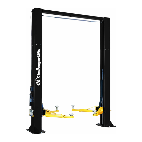
Installation, Operation & Maintenance Manual
Two Post Surface Mounted Lift
M
15000-3S
15000-SPRINTER
&
ODELS
15,000
C
- 3750
P
A
LB
APACITY
LB
ER
RM
2311 South Park Rd Louisville, Kentucky 40219
Email:
Web site:
sales@challengerlifts.com
www.challengerlifts.com
/
Office 800-648-5438
502-625-0700 Fax 502-587-1933
IMPORTANT:
READ THIS MANUAL COMPLETELY BEFORE
INSTALLING or OPERATING LIFT
Rev. 8/13/19
Advertisement
Table of Contents

Subscribe to Our Youtube Channel
Related Manuals for Challenger Lifts 15000-SPRINTER 15000-3S


Summary of Contents for Challenger Lifts 15000-SPRINTER 15000-3S
- Page 1 Installation, Operation & Maintenance Manual Two Post Surface Mounted Lift 15000-3S 15000-SPRINTER & ODELS 15,000 - 3750 APACITY 2311 South Park Rd Louisville, Kentucky 40219 Email: Web site: sales@challengerlifts.com www.challengerlifts.com Office 800-648-5438 502-625-0700 Fax 502-587-1933 IMPORTANT: READ THIS MANUAL COMPLETELY BEFORE INSTALLING or OPERATING LIFT Rev.
-
Page 2: General Specifications
Model 15000-3S & 15000-SPRINTER Installation, Operation and Maintenance ENERAL PECIFICATIONS 15000-3S 15002-3S See Figure 1 15000-SPRINTER 15000-SPRINTER 174” [14’-6”] 198” [16’-6”] Column Height 167” [13’-11”] 191” [15’-11”] Floor to Overhead Switch 82” Rise Height (Screw Pads Highest Position) 5 1/2” to 13" Screw Pad Height 119 7/8”... -
Page 3: Vertical Clearance
Model 15000-3S & 15000-SPRINTER Installation, Operation and Maintenance ERTICAL LEARANCE EAD ENTIRE MANUAL BEFORE ASSEMBLING INSTALLING OPERATING OR SERVICING THIS Check the height of the area where the lift is to be EQUIPMENT installed. Clearance should be calculated based on ROPER MAINTENANCE AND INSPECTION IS NECESSARY the full raised height of the lift. -
Page 4: Installation
Do this for your own 5/16” allen wrench protection. g. Needle nose pliers h. Hammer drill with 3/4” diameter carbide tipped Challenger Lifts NOTIFY AT ONCE if any hidden bits loss or damage is discovered after receipt. - Page 5 Model 15000-3S & 15000-SPRINTER Installation, Operation and Maintenance VERHEAD NCHORING 12) Before raising overhead into position install 4 5) The anchor bolts must be installed at least 8” each (2 per column) hex flange bolts and nuts in from any crack, edge, or expansion joint. bottom hole of column extension (see Fig.
- Page 6 Model 15000-3S & 15000-SPRINTER Installation, Operation and Maintenance 14) Install Overhead Limit Switch to the Overhead 16) Assemble the cable trapping hardware with a Beam using the rear set of holes on the Power 3/8”-16 x 3” Lg bolt with (2) 3/8”-16 flange nuts at Side of the lift.
- Page 7 Model 15000-3S & 15000-SPRINTER Installation, Operation and Maintenance YNCHRONIZER ABLES YDRAULICS 17) Manually raise the carriages to a common lock IMPORTANT – To insure proper hose fitting seal position, to gain access to the top of the without damage to the fitting follow this carriage.
- Page 8 Model 15000-3S & 15000-SPRINTER Installation, Operation and Maintenance 25) Ensure that the Idler Side hose is not twisted and laying flat overhead channel. 22) Secure hose with clamps. Start with the tab (Serpentine any extra length in the overhead and connection in the column extension.
-
Page 9: Lock Release
Model 15000-3S & 15000-SPRINTER Installation, Operation and Maintenance ELEASE 30) Assemble the fittings to the air valve, Fig. 15, with the barbed fitting (3/8” hose barb x 1/8NPT) in port marked “1”, the elbow (1/8” push-lock x 1/8NPT) in port “2”, and nothing in the center port “3”... -
Page 10: Arm Installation
Model 15000-3S & 15000-SPRINTER Installation, Operation and Maintenance NSTALLATION LECTRICAL 36) Lubricate the arm pin or carriage arm pin hole See Figure 20 for the following steps. with “anti-seize” and install the arms. Insure that 40) Wire tie Limit Switch cord to column hydraulic the arm restraint gears engage and disengage line and power unit line. -
Page 11: Final Adjustments
Model 15000-3S & 15000-SPRINTER Installation, Operation and Maintenance cylinder rod, the cylinder will apear to be INAL DJUSTMENTS leaking. YDRAULICS YNCHRONIZING ABLES 44) Lower the lift to the floor and raise the lift 49) Raise lift and insure carriages lower into same approximately one foot. - Page 12 Model 15000-3S & 15000-SPRINTER Installation, Operation and Maintenance Wiring Diagram FOR SINGLE PHASE FIELD CONECTIONS (Normally Open) FIELD CONECTIONS FOR THREE PHASE FACTORY WIRED FOR 208−240V RECONNECTIONS FOR 440−480V Fig 20 – Electrical Wiring Diagram Page 12 Rev. 8/13/19 15-3S-IOM-A.doc...
-
Page 13: Operation Procedure
Model 15000-3S & 15000-SPRINTER Installation, Operation and Maintenance 90 ALI Safety Tips card; ANSI/ALI ALOIM-2008, PERATION ROCEDURE American National Standard for Automotive Lifts- AFETY OTICES AND ECALS Safety Requirements for Operation, Inspection and Maintenance; and in the case of frame This product is furnished with graphic safety engaging lift, ALI/LP-GUIDE, Vehicle Lifting warning labels, which are reproduced on... - Page 14 Model 15000-3S & 15000-SPRINTER Installation, Operation and Maintenance IFTING A EHICLE OSS OF POWER 1) Insure that the lifting arms are parked, out to full If for any reason the lift will not raise off the locks or drive thru position. the locks will not retract, consult factory authorized personnel.
-
Page 15: Maintenance
Check for loose or broken parts. Check hydraulic system for fluid leaks. Check adapters for damage or excessive wear. Replace as required with genuine Challenger Lifts parts. Check lock release activation. When properly adjusted, the idler column lock should rest firmly against the back of the column when engaged and against the spring mount tab when disengaged. -
Page 16: Parts Breakdown
12117H COLUMN EXTENSION PACK (16’-6” O.A. Ht.) Items (2, 50, 64, 65, 66, 67) Replace all worn, damaged, or broken parts with parts approved by Challenger Lifts Inc. or with parts meeting Challenger Lifts Inc. specifications. Contact your local Challenger Lifts Parts Distributor for pricing and availability. - Page 17 Model 15000-3S & 15000-SPRINTER Installation, Operation and Maintenance PARTS BREAKDOWN (continued) Fig B. Lock-Power/Idler Page 17 Rev. 8/13/19 15-3S-IOM-A.doc...
- Page 18 LOCK WELD 37072 SNAP ON LOCK COVER Replace all worn, damaged, or broken parts with parts approved by Challenger Lifts Inc. or with parts meeting Challenger Lifts Inc. specifications. Contact your local Challenger Lifts Parts Distributor for pricing and availability.
- Page 19 3/8” -16 x 3/4” LG. HEX FLANGE BOLT A1154 3/8” -16 HEX FLANGE NUT Replace all worn, damaged, or broken parts with parts approved by Challenger Lifts Inc. or with parts meeting Challenger Lifts Inc. specifications. Contact your local Challenger Lifts Parts Distributor for pricing and availability.
- Page 20 12019 SYNC. CABLE ASSEMBLY (16’-6” O.A. Ht.) Replace all worn, damaged, or broken parts with parts approved by Challenger Lifts Inc. or with parts meeting Challenger Lifts Inc. specifications. Contact your local Challenger Lifts Parts Distributor for pricing and availability.
- Page 21 Model 15000-3S & 15000-SPRINTER Installation, Operation and Maintenance PARTS BREAKDOWN (continued) Fig F. Carriage & 3-Stage Arms Page 21 Rev. 8/13/19 15-3S-IOM-A.doc...
- Page 22 ARM ASSEMBLY, 3-STAGE Items (77, 84, 85, 86, 87, 88, 89, 90, 95, 96,101) Replace all worn, damaged, or broken parts with parts approved by Challenger Lifts Inc. or with parts meeting Challenger Lifts Inc. specifications. Contact your local Challenger Lifts Parts Distributor for pricing and availability.
Need help?
Do you have a question about the 15000-SPRINTER 15000-3S and is the answer not in the manual?
Questions and answers