Challenger Lifts 44030 Installation, Operation & Maintenance Manual
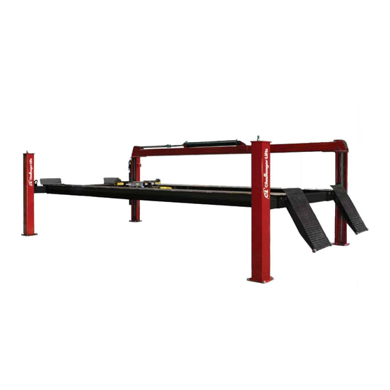
Heavy duty four post lift, 30,000 lbs capacity
Hide thumbs
Also See for 44030:
- Installation, operation & maintenance manual (25 pages) ,
- Installation, operation & maintenance manual (25 pages)
Table of Contents
Advertisement
Installation, Operation & Maintenance Manual
H
D
EAVY
UTY
F
P
L
OUR
OST
IFT
30,000 lbs Capacity
Model 44030
Model 44030E
Model 44030X
200 Cabel Street, P.O. Box 3944 Louisville, Kentucky 40201-3944
Email:
Web site:
sales@challengerlifts.com
www.challengerlifts.com
Office 800-648-5438 / 502-625-0700 Fax 502-587-1933
IMPORTANT: READ THIS MANUAL COMPLETELY
BEFORE INSTALLING or OPERATING LIFT
File: 44030-STD-4-07
Rev: 4/2007
Advertisement
Table of Contents

Related Manuals for Challenger Lifts 44030


Summary of Contents for Challenger Lifts 44030
- Page 1 Installation, Operation & Maintenance Manual EAVY 30,000 lbs Capacity Model 44030 Model 44030E Model 44030X 200 Cabel Street, P.O. Box 3944 Louisville, Kentucky 40201-3944 Email: Web site: sales@challengerlifts.com www.challengerlifts.com Office 800-648-5438 / 502-625-0700 Fax 502-587-1933 IMPORTANT: READ THIS MANUAL COMPLETELY...
-
Page 3: Cautions And Warnings
2. Read the installation manual before installing the lift. 3. This lift is a four post lift which requires a minimum (44030.) 15’-6” x 30’-0” / (44030E.) 15’-6” x 35’-0” / (44030X.) 15’-6” x 40’-0” bay area. If 3 feet track extensions are purchased then increase the length in increments of the 3’-0”... -
Page 4: Tools Required
Model 44030 Series Installation, Operation & Maintenance TOOLS REQUIRED Concrete rotary hammer drill with ¾” carbide bit Open End Wrenches: 7/16”, 1/2”, 9/16”, 11/16”, 3/4” & 1 1/8” Ratchet Driver Sockets: ¼”, 1/2”, 3/4” X 1/2” deep Allen Wrenches: 3/16”, 1/4” & 5/16”... -
Page 5: Installation Instructions
Model 44030 Series Installation, Operation & Maintenance INSTALLATION INSTRUCTIONS 1. Standard area required for four post lift is a minimum of (44030) 15’-6” x 30’-0”’ or (44030E) 15’-6” x 35’-0” or (44030X) 15’-6” x 40’-0” area. If 3 feet track extensions are purchased then increase the length in increments of the 3’-0”... - Page 6 Model 44030 Series Installation, Operation & Maintenance 11. Next using the 3/8 x 1 ½ shoulder screw provided, connect the Cross Rail chain to the chain anchor welded to the base plate of the Main side Leg ( see Fig. 5C Next move the Cross Rail over the chain connector.
- Page 7 Model 44030 Series Installation, Operation & Maintenance 22. Step #12 is to locate the Track Weldm’t. (44030, 2 pcs, ALIF-430-037-XX), (44030E, 2 pcs, ALIF-430-237), (44030X, 2 pcs, ALIF-430-337) and position them on top of the Cross Rails as shown in Fig. #5F. Hold 62” inside Track Weldm’t.
-
Page 8: Owner/Operator Checklist
Model 44030 Series Installation, Operation & Maintenance Owner/Operator Checklist SAVE THESE INSTRUCTIONS deliver them to owner/user/employee along with other materials furnished with this lift. Demonstrate the operation of the lift to the owner/operator and review correct and safe lifting procedures using the Lifting It Right booklet as a guide. -
Page 9: Important Safety Instructions
Check hydraulic system for fluid leaks. • Check lock release activation. Weekly • Check chains and sheaves for wear or damage. Replace as required with genuine Challenger Lifts parts. • Inspect lock mechanism for proper function. Monthly • Torque concrete anchor bolts to 80 ft-lbs. - Page 10 Model 44030 Series Installation, Operation & Maintenance Page 10...
- Page 11 Model 44030 Series Installation, Operation & Maintenance Page 11...
- Page 12 Cylinder Chain Connector ALIF-430-085 BL834, 91 Pitch Male Ends, Short Top Rail Chain ALIF-430-086 44030, BL834, 325 Pitch Male Ends, Long Top Rail Chain ALIF-430-286 44030E, BL834, 385 Pitch Male Ends, Long Top Rail Chain ALIF-430-386 44030X, BL834, 445 Pitch Male Ends, Long Top Rail Chain GL-12-056 4”...
- Page 13 Model 44030 Series Installation, Operation & Maintenance PART NUMBER DESCRIPTION QTY. GL-12-056 4” Dia. Chain Sheave SPC-2001 1/8 Straight Push-On Fitting 6498K43 Clevis, Pin & Ext. Retainer Ring 6498K337-2.00 1 1/16 Dia. x 2” Stroke Cylinder 90126A031 3/8 SAE Flat Washer...
-
Page 14: Misc Parts
Model 44030 Series Installation, Operation & Maintenance PART NUMBER DESCRIPTION QTY. Misc. Parts 14R1C00080 Pressure Limiter 296-2-LT Pneumatic Control Valve 3225T6 3/4 Rubber-Cushion Steel Loop 5404-04-04 1/4 MNPT Hex Nipple 5406-04-02 1/4MNPT X 1/8FNPT Reducer 6534K46 1/4 MNPT Pneumatic Hose Coupling 6801-LL-06-06 3/8 MJIC x 3/8 MORB 90 Deg. - Page 15 Model 44030 Series Installation, Operation & Maintenance Page 15...
- Page 16 Model 44030 Series Installation, Operation & Maintenance Page 16...
- Page 17 Model 44030 Series Installation, Operation & Maintenance Page 17...
- Page 18 Model 44030 Series Installation, Operation & Maintenance Page 18...
- Page 19 Model 44030 Series Installation, Operation & Maintenance Page 19...
- Page 20 Model 44030 Series Installation, Operation & Maintenance Page 20...
- Page 21 Model 44030 Series Installation, Operation & Maintenance Page 21...
- Page 22 Model 44030 Series Installation, Operation & Maintenance Page 22...
- Page 23 Model 44030 Series Installation, Operation & Maintenance Page 23...
- Page 24 Model 44030 Series Installation, Operation & Maintenance Page 24...
- Page 25 Model 44030 Series Installation, Operation & Maintenance Page 25...