Table of Contents
Advertisement
Quick Links
I
NSTALLATION
Surface Mounted Lift
2311 South Park Rd., Louisville, Kentucky 40219
Email:
sales@challengerlifts.com
Office 877-771-5438/ 502-583-5438 Fax 502-583-5488
IMPORTANT:
, O
& M
PERATION
Two Post
M
ODEL
15,000
. C
LBS
APACITY
3750
.
LBS
PER
Web site:
READ THIS MANUAL COMPLETELY BEFORE
INSTALLING or OPERATING LIFT
AINTENANCE
E15
A
RM
www.challengerlifts.com
M
ANUAL
Rev.02/14/19
Advertisement
Table of Contents

Related Manuals for Challenger Lifts E15


Summary of Contents for Challenger Lifts E15
- Page 1 & M NSTALLATION PERATION AINTENANCE ANUAL Two Post Surface Mounted Lift ODEL 15,000 APACITY 3750 2311 South Park Rd., Louisville, Kentucky 40219 Email: Web site: sales@challengerlifts.com www.challengerlifts.com Office 877-771-5438/ 502-583-5438 Fax 502-583-5488 IMPORTANT: READ THIS MANUAL COMPLETELY BEFORE INSTALLING or OPERATING LIFT Rev.02/14/19...
-
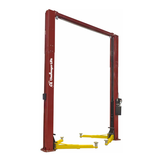
Page 2: General Specifications
Model E15 Installation, Operation and Maintenance ENERAL PECIFICATIONS See Figure 1 Rise Height (Screw Pads Highest Position) 77 3/4" (1975 mm) Overall Height 14’-6” ( 16’-6” ( 4420mm) or 5030mm) Overall Width 147 1/16" (3735 mm) Drive-Thru Clearance 109 3/8"... -
Page 3: Vertical Clearance
Model E15 Installation, Operation and Maintenance Safety decals similar to those shown here ERTICAL LEARANCE are found on a properly installed lift. Be Check the height of the area where the lift is to sure that all safety decals have been be installed. -
Page 4: Installation
Model E15 Installation, Operation and Maintenance ECEIVING NSTALLATION The shipment should be thoroughly inspected MPORTANT Always wear safety glasses while installing as soon as it is received. The signed bill of lift. lading is acknowledgement by the carrier of OOLS... - Page 5 Model E15 Installation, Operation and Maintenance NCHORING 4) The anchor bolts must be installed at least 8” from any crack, edge, or expansion joint. 5) Use a concrete hammer drill with a 3/4 inch carbide bit. Tip diameter should conform to ANSI Standard B94.12-1977 (.775 to .787).
- Page 6 Model E15 Installation, Operation and Maintenance Fig. 7 – Hose Routing Fig. 6 – Synchronizing Cables 25) B ERTAIN ITTINGS AND ONNECTIONS ARE & H OWER YDRAULIC INES IGHT T IS THE INSTALLERS RESPONSIBILITY TO ENSURE . Fill the Power Unit with three...
- Page 7 Model E15 Installation, Operation and Maintenance ELEASE 27) Install Lock Release Rod, Clevis, and Knob to the Power Column Lock using one M10 Nut. 28) Attach Mechanical Lock Release Cable Assembly to each lock pawl. See Fig. 9. Fig. 11 –...
- Page 8 Model E15 Installation, Operation and Maintenance 40) Connect Contactor to Power unit as shown. INAL DJUSTMENTS Connect Contactor to suitable electrical YDRAULICS source as shown. 43) Lower the lift to the floor and raise the lift IMPORTANT: FTER WIRING BEEN approximately one foot.
- Page 9 Model E15 Installation, Operation and Maintenance Wiring Diagram FOR SINGLE PHASE FIELD CONNECTIONS (Normally Open) FOR THREE PHASE FACTORY WIRED FOR 208−240V RECONNECTIONS FOR 440−480V Fig 13 – Electrical Wiring Diagram Page 9 Rev. 2/14/19 E15-IOM-A.
-
Page 10: Operation Procedure
Model E15 Installation, Operation and Maintenance 90 ALI Safety Tips card; ANSI/ALI ALOIM-2008, PERATION ROCEDURE American National Standard for Automotive Lifts- AFETY OTICES AND ECALS Safety Requirements for Operation, Inspection and Maintenance; and in the case of frame This product is furnished with graphic safety... - Page 11 Model E15 Installation, Operation and Maintenance IFTING A EHICLE OSS OF POWER 1) Ensure that the lifting arms are parked, out to If for any reason the lift will not rise off the locks full drive thru position. or the locks will not retract, consult factory authorized personnel.
- Page 12 Model E15 Installation, Operation and Maintenance AINTENANCE Monthly To avoid personal injury, permit only qualified Torque concrete anchor bolts to 80 ft-lbs. personnel to perform maintenance on this Check overhead shutoff switch. While raising equipment. Maintenance personnel should follow lockout/tagout instructions per ANSI Z244.1.
- Page 13 X10-040 M12 HEX NUT IMPORTANT Replace all worn, damaged, or broken parts with parts approved by Challenger Lifts Inc. or with parts meeting Challenger Lifts Inc. specifications. Contact your local Challenger Lifts Parts Distributor for pricing and availability. (Call Challenger Lifts Inc. (502) 625-0700 for the Parts Distributor in your area) Page 13 Rev.
- Page 14 X10-040 M12 NUT IMPORTANT Replace all worn, damaged, or broken parts with parts approved by Challenger Lifts Inc. or with parts meeting Challenger Lifts Inc. specifications. Contact your local Challenger Lifts Parts Distributor for pricing and availability. (Call Challenger Lifts Inc. (502) 625-0700 for the Parts Distributor in your area) Page 14 Rev.
- Page 15 AB-9367-DLH POWER UNIT 1PH 230V 50/60Hz IMPORTANT Replace all worn, damaged, or broken parts with parts approved by Challenger Lifts Inc. or with parts meeting Challenger Lifts Inc. specifications. Contact your local Challenger Lifts Parts Distributor for pricing and availability.
- Page 16 E15-01-09 LOWER SHEAVE PIN IMPORTANT Replace all worn, damaged, or broken parts with parts approved by Challenger Lifts Inc. or with parts meeting Challenger Lifts Inc. specifications. Contact your local Challenger Lifts Parts Distributor for pricing and availability. (Call Challenger Lifts Inc. (502) 625-0700 for the Parts Distributor in your area) Page 16 Rev.
- Page 17 105D B12067 ADAPTER BASE Replace all worn, damaged, or broken parts with parts approved by Challenger Lifts Inc. or with parts meeting Challenger Lifts Inc. specifications. Contact your local Challenger Lifts Parts Distributor for pricing and availability. (Call Challenger Lifts Inc. (502) 625-0700 for the Parts Distributor in your area) Page 17 Rev.
- Page 18 12073 5/16-18 x ½ BUTTON HD SCREW Replace all worn, damaged, or broken parts with parts approved by Challenger Lifts Inc. or with parts meeting Challenger Lifts Inc. specifications. Contact your local Challenger Lifts Parts Distributor for pricing and availability.
Need help?
Do you have a question about the E15 and is the answer not in the manual?
Questions and answers