
Related Manuals for Challenger Lifts 44012LR


Summary of Contents for Challenger Lifts 44012LR
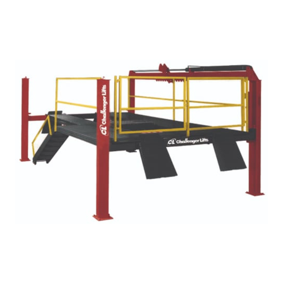
- Page 1 MANUAL FOR 44012LR EXT. 4 POST LUBE RACK LIFT Challenger Lifts, Inc 200 Cabel Street Louisville, KY. 40206 Phone: (502) 625-0700 Fax: (502) 625-0711 E-MAIL: sales@challengerlifts.com...
- Page 2 Rev. - INTRODUCTION The four post lift consists of four vertical posts with runway tracks between the posts. The lifting is done by a hydraulic cylinder coupled to heavy duty leaf chains, which roll over sealed roller bearings. A 2 H.P. power unit supplies up to 2,500 p.s.i.
-
Page 3: Tools Required
TOOLS REQUIRED Concrete rotary hammer drillwith 3/4” carbide bit Open end wrenches: 1/2”, 9/16”, 11/16”, 3/4” Ratchet driver Sockets: 3/4”, 1/2” deep 12” crescent wrench Hammer Needle nose pliers Level Fish tape 25’ tape measure Chalk line Small drift punch Step ladder 4 wooden blocks (2 x 4’s) 4 gallons non-detergent hydraulic fluid 10 wt. -
Page 4: Anchoring Tip Sheet
ANCHORING TIP SHEET 1. Anchors must be at least 5” from the edge of the slab or any seam. 2. Use a concrete hammer drill with a 3/4 carbide bit. 3. Do not use a worn bit. 4. Drill in a perpendicular line with the hole. 5. -
Page 5: Installation
INSTALLATION 1. Determine the location for the lift. Keep in mind overhead clearances. Ten feet is the minimum recommended ceiling height. Allow 4 in. for approach ramp. 2. Determine which side of the lift the toprail and power unit are to be on. This is called the MAINSIDE. - Page 6 shipping. NOTE: The set of holes nearest the safety rod hole will not take a flat washer. 8. Raise toprail/leg assembly by pressing and walking the unit into the upright position. Make sure the safety rod holes referred to in Fig. 7 are still aligned.
- Page 7 14. Position both crossrails in front of a mainside leg, with the machined connector towards the mainside leg. Using the Master Link provided, connect the crossrail chain to the chain anchor welded to the base plate of the mainside leg. See Fig. 9. ***** IMPORTANT ***** THE MASTER LINK MUST HAVE THE CENTER LINK, AND IT MUST BE IN A VERTICAL POSITION.
- Page 8 chain to each crossrail connector using 5/16 x 3 1/2” Shoulder bolt and nuts. Do not substitute this bolt!!!! Repeat on other crossrail. Replace fitting on cylinder. 21. Attach the power unit at its location on the mainside leg with supplied hardware.
- Page 9 move across the rack at the bottom of the toprail. At the top of the lift’s travel, pull down the toprail safety latch banjo until the Reset locks it open. Adjust and plumb cross rails and legs as necessary. When you are positive the lift is moving freely, you may finally drill and install the anchor bolts in the offside legs.
-
Page 10: Periodic Maintenance
objects that might interfere with the operation of the lift and it’s safety latches such as: tools, air hoses, shop equipment, etc. 2. Slowly drive the vehicle fully onto the tracks. Have someone outside the vehicle guide the vehicle down the tracks. 3. -
Page 11: Parts & Shipping List
excessive wear between the chain and roller. PARTS & SHIPPING LIST PART NUMBER DESCRIPTION QTY. 2501-06-06 3/8MNPT x 3/8MJIC 90 Deg. Adapter 5304ZZ DS Bearings 6801-LL-06-06 0.375M x 0.375F 90 Deg. NPT Adapter w/O-ring 7130K55 11” Black Ties 80050 BL634 Master Link 90126A033 ½... - Page 12 GL-9-056 1/16 x 1 x 2 ¾ Steel Shim GL-9-112 ¼ x 1 x 2 ¾ Steel Shim GL-12-002-XX Mainside Leg Weldm’t. GL-12-003-XX Mainside Leg Weldm’t. with P/U Mount GL-12-004-XX Offside Leg Weldm’t. GL-12-049 Offside Leg Chain Connector GL-12-052 Safety Latch Rod Lube Rack Bolt Box Kit ALRK-412-BHDWE 90126A031...
- Page 13 90108A036 ¾ USS Flat Washer 97801A104 1/8 x 2 Lg. Nail 98410A128 0.750 Dia. Retainer Ring ALIF-412-012 Packing Pin 1.10 O.D. x 4 ½” Safety Latch Spring C1100-112-4500M Cross Rail Weldm’t. ALRK-412-002-XX GL-12-055 2.25 Dia. Pulley GL-12-057 Cross Rail Chain Connector GL-12-078 Safety Stop Plate GL-12-089-XX...
Need help?
Do you have a question about the 44012LR and is the answer not in the manual?
Questions and answers