Table of Contents
Advertisement
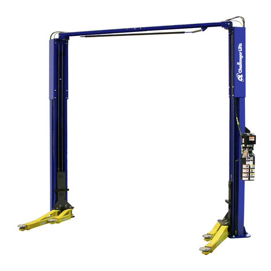
Installation, Operation & Maintenance Manual
Two Post
Surface Mounted Lift
M
SA10
ODEL
(This lift may be installed either symmetrically or asymmetrically)
10,000
. C
(
LBS
APACITY
2500 lbs. per Arm)
200 Cabel Street, P.O. Box 3944 Louisville, Kentucky 40201-3944
Email:
Web site:
sales@challengerlifts.com
www.challengerlifts.com
/
Office 800-648-5438
502-625-0700 Fax 502-587-1933
IMPORTANT:
READ THIS MANUAL COMPLETELY BEFORE
INSTALLING or OPERATING LIFT
Rev. 10/01/15
Advertisement
Table of Contents

Related Manuals for Challenger Lifts SA10


Summary of Contents for Challenger Lifts SA10
- Page 1 Installation, Operation & Maintenance Manual Two Post Surface Mounted Lift SA10 ODEL (This lift may be installed either symmetrically or asymmetrically) 10,000 APACITY 2500 lbs. per Arm) 200 Cabel Street, P.O. Box 3944 Louisville, Kentucky 40201-3944 Email: Web site: sales@challengerlifts.com www.challengerlifts.com...
-
Page 2: Specifications
Model SA10 Installation, Operation and Maintenance ENERAL PECIFICATIONS See Figure 1 SA10 (Symmetric Install) SA10 (Asymmetric Install) Rise Height * 74 1/2" (1892mm) 142 1/2” (3620mm) Overall Height (Cylinder) 136 1/2" 142 1/2" (3467mm/3620mm) Overhead Height (Adjustable) 160 1/2" / 166 1/2” (4077mm/4230mm) -
Page 3: Vertical Clearance
Model SA10 Installation, Operation and Maintenance ERTICAL LEARANCE EAD ENTIRE MANUAL BEFORE ASSEMBLING INSTALLING OPERATING OR SERVICING THIS Check the height of the area where the lift is to be EQUIPMENT installed. Clearance should be calculated based on ROPER MAINTENANCE AND INSPECTION IS the full raised height of the lift. -
Page 4: Installation
Model SA10 Installation, Operation and Maintenance ECEIVING NSTALLATION The shipment should be thoroughly inspected as MPORTANT Always wear safety glasses while installing lift. soon as it is received. The signed bill of lading is OOLS MINIMUM REQUIRED acknowledgement by the carrier of receipt in good a. - Page 5 Model SA10 Installation, Operation and Maintenance 4) Assemble Overhead Mounting Bracket to the NCHORING Column Extension using (4 sets) M12 x 25 Hex 7) The anchor bolts must be installed at least 8” bolts, flat washers, lock washers, and nuts.
- Page 6 Model SA10 Installation, Operation and Maintenance VERHEAD YMMETRIC 16) For Asymmetric installation, skip to Step 19. 14) Assemble two Overhead pieces using (6 sets) M10 x 20 bolt, nut, flat washer, and lock washer 17) With the Overhead positioned UPSIDE DOWN, as shown in Fig 6.
- Page 7 Model SA10 Installation, Operation and Maintenance SYMMETRIC NCHORING 19) Disassemble sheave assemblies from each end. 21) Check Idler Column shimming. Use additional shims (see Fig 5) to remove any gaps that may With the Overhead positioned UPSIDE DOWN, have been created while installing Overhead.
- Page 8 Model SA10 Installation, Operation and Maintenance YNCHRONIZER ABLES 24) Carriages should be setting in first lock position as mentioned in an earlier step. 25) Each cable is pre-routed around base sheave and up through the bottom of the Carriage. Attach that end of the Synchronizing Cable to the proper carriage tab according to Fig 13a.
-
Page 9: Hydraulic Hoses
Model SA10 Installation, Operation and Maintenance YDRAULIC OSES 32) Assemble Power Unit, Tee Fitting, and hoses together as shown in Fig 17. Use (4 sets) M8 30) Attach Power Hose to Cylinder Fitting at the bolt, nut, flat washer, and lock washer to attach bottom of the Power Column as shown in Fig 15 Power Unit to column bracket. -
Page 10: Lock Release
Model SA10 Installation, Operation and Maintenance ELEASE 34) While the carriages are still sitting in the locks from the previous steps, route the Lock Release Cable assembly (Loop End) through the Idler Column opening, around the pulley and attach to the Lock Release Cam as seen in Fig 19a. - Page 11 Model SA10 Installation, Operation and Maintenance YMMETRIC NSTALLATION 38) For Asymmetric installation, skip to step 40. 40) Extend the Foot Pad to both extents and apply “anti-seize” to the three retaining rings and Ensure the Inner Gear is positioned on the arms as shown in Fig 21.
- Page 12 Model SA10 Installation, Operation and Maintenance OLUMN ECAL LACEMENT rise.) If lubricant is not wiped clean from the cylinder rod, the cylinder may appear to be 48) Clean the surface of the columns before placing leaking. the decals. YNCHRONIZING ABLES 49) Apply the Safety Decals (Pg.
- Page 13 Model SA10 Installation, Operation and Maintenance FIELD CONECTIONS (Normally Open) ...
-
Page 14: Operation Procedure
Model SA10 Installation, Operation and Maintenance Owner/Employer shall establish WNER PERATOR HECKLIST procedures to periodically maintain the lift in 62) Demonstrate the operation of the lift to the accordance with lift manufacturer’s owner/operator and review correct and safe instructions or ANSI/ALIOIM-2008, American... -
Page 15: Lifting A Vehicle
Model SA10 Installation, Operation and Maintenance IFTING A EHICLE 5) Continue to lower the vehicle until the carriages stop against the base plate. Retract the 1) Ensure that the lifting arms are parked, out to extension arms, and park them. -
Page 16: Maintenance
Model SA10 Installation, Operation and Maintenance AINTENANCE To avoid personal injury, permit only qualified personnel perform maintenance this equipment. Maintenance personnel should follow lockout/tagout instructions per ANSI Z244.1. The following maintenance points are suggested as the basis of a routine maintenance program. -
Page 17: Parts Breakdown
Replace worn, damaged, or broken parts with parts approved by Challenger Lifts, Inc. or with parts meeting Challenger Lifts Inc. specifications. Contact a local Challenger Lifts parts distributor for pricing and availability. Call Challenger Lifts Inc. at (502) 625-0700 for the distributor in your area. - Page 18 Model SA10 Installation, Operation and Maintenance Item # Part # Qty. Description Item # Part # Qty. Description 3W-01-01P Power Column Weld HEXHM1030 M10 x 30 Hex Bolt 3W-01-01I Idler Column Weld X10-073 M10 Flat Washer 3W-01-05PA Power Col. Extension (Std. Height)
- Page 19 Model SA10 Installation, Operation and Maintenance Item # Part # Qty. Description Item # Part # Qty. Description 3W-10-15A Hose Clamp X10-033 M6 Lock Washer MR6-002 M10 x 20 Hex Bolt 3W-01-08 Lock Paw 3W-01-20 Flexible Guide Tube 3W-01-14 Lock Clevis Pin...
Need help?
Do you have a question about the SA10 and is the answer not in the manual?
Questions and answers